


13
Make sure the generator battery is fully charged, prop-
erly installed and interconnected, and ready for use.
Check to ensure that there are no loose electrical con-
nections. Restrain any loose wires to keep them clear
of any moving generator set components.
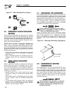
3.1 USING AN ENGINEERED “GTS”
TRANSFER SWITCH
When required, the pre-packaged standby generator
can be installed with an engineered “GTS” type auto-
matic transfer switch.
In this application, the GTS is responsible for utility
sensing, weekly exercising, and load transferring.
Position two of the four-position dip switch is used to
turn over this control to the GTS.
Pos2 ON — GTS Application
• The control board will NOT monitor utility.
• The control board will NOT perform a weekly exer-
cise. (The five red LEDs will not flash in this
mode.)
• The control board will NOT activate the transfer
output.
• The control board WILL monitor all engine condi-
tions and shut down on all the faults listed in this
document.
Pos2 OFF — ATS Application (Included switch)
• The control board will perform all of the automat-
ic features listed in this document.
• The two-wire start connections should NOT be
used.
GTS Mode Operation
When in GTS mode, the control board will respond
as follows based on the AUTO/OFF/MANUAL switch
position.
OFF — The generator will not start and run in this
position.
MANUAL — The control board will start and run the
generator whenever the switch is in the manual posi-
tion.
AUTO — The control board will monitor the two-wire
start circuit. When a two-wire start is issued the con-
trol board will immediately start and run the genera-
tor. Whe the two-wire start is removed the control
board will immediately stop the generator.
NOTE:
If the generator is installed in conjunction with an
engineered GTS type transfer switch, refer to the
applicable transfer switch manual for exact oper-
ating parameters and timing sequences.
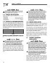
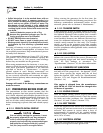
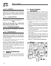
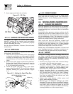
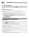
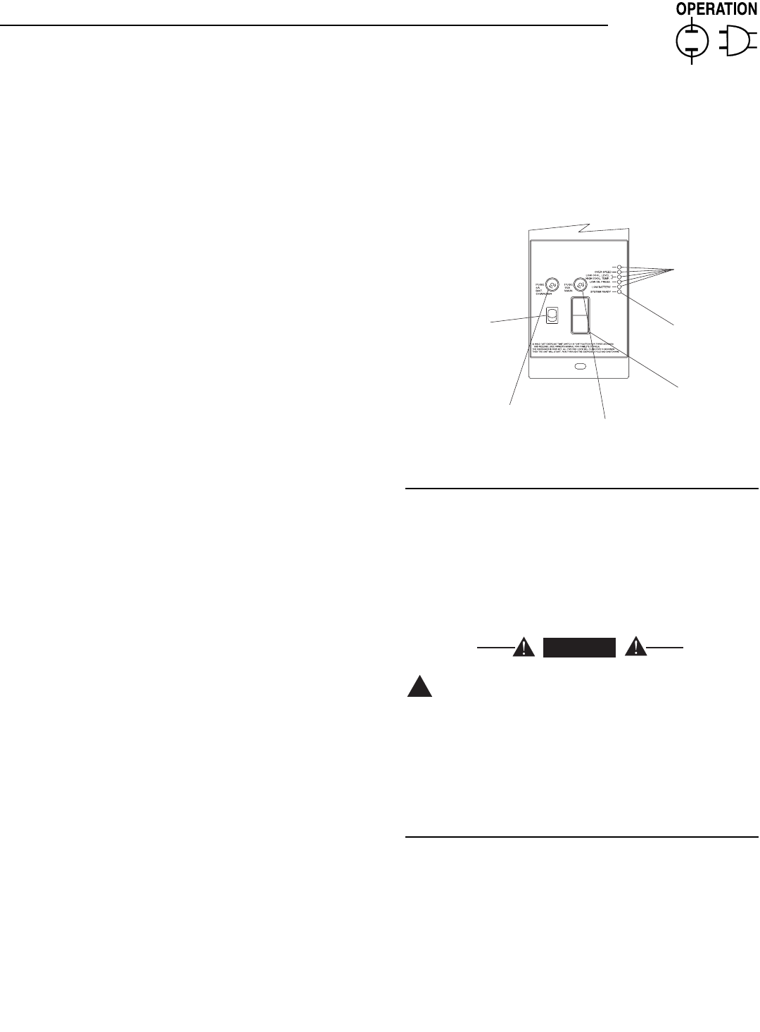
3.2 CONTROL CONSOLE
COMPONENTS
The components of a home standby generator control
console (Figure 3.1) are as follows:
Figure 3.1 - Home Standby Generator Panel
3.2.1 AUTO/OFF/MANUAL SWITCH
Use this three-position switch as follows:
• Set the switch to AUTO for fully automatic opera-
tion. See “Automatic Operation” (Section 3.5).
• Set switch to MANUAL position to crank and start
the generator engine.
• Set switch to OFF position to shut down an oper-
ating engine. With OFF selected, operation will not
be possible.
With switch set to AUTO, engine can crank and
start suddenly without warning. Such automat-
ic start up normally occurs when utility source
voltage drops below a pre-set level. To prevent
possible injury that might be caused by such
sudden starts, set AUTO/OFF/ MANUAL switch
to OFF before working on or around the unit.
Then, place a “DO NOT OPERATE” tag on con-
trol console.
3.2.2 FAULT INDICATOR LEDS
These LEDs turn ON when one of the following
engine faults occurs and the engine shuts down.
• Low Oil Pressure
• Overcrank
• Low Battery
• Overspeed/RPM Sensor Loss
• High Coolant Temperature/Low Coolant Level
See Section 1.7 for further explanation of engine pro-
tection functions.
!
DANGER
E
U
S
UU
F
F
E
U
S
UU
F
(
SEE OWNER'S MANUAL FOR COMPLETE LED DETAILS
)
5
FLA
S
HIN
G
RED LED'
S
= EXER
C
I
S
ER N
O
T
S
E
T
FLA
S
HIN
G
G
REEN LED = N
O
U
TILITY
S
EN
SE
TO SET EXERCISER TIME
1) PLACE AUTO/OFF/MANUAL SWITCH TO AUTO POSITION.
(
IN AUTO MODE ONLY
)
SOLID GREEN LED = SYSTEM READY, UTILITY POWER O
N
OFF
EXER
C
I
SE
TIME
ON
S
E
T
LED INDI
C
AT
O
R
S:
RED LED'
S
= INDIVID
U
AL FA
U
L
T
M
AN
U
A
L
O
F
F
A
U
T
O
0E7194
O
VER
C
RAN
K
A
U
T
O/O
FF
/
MAN
U
A
L
S
WIT
CH
1
5
A F
USE
MAI
N
P
O
WE
R
4A F
USE
BATTERY
C
HAR
G
E
R
S
E
T
EXE
C
I
S
E
R
TIME
S
WIT
CH
RED LED
G
REEN LE
D
Section 3 - Operation
40kW Liquid-cooled Generators