


10
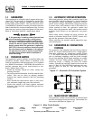
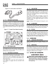
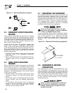
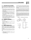
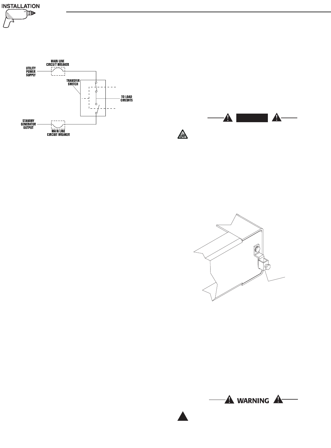
Figure 2.1 – Basic Standby Electric System
2.5 EMERGENCY CIRCUIT ISOLATION
METHOD
This prevents overloading the generator by keeping
electrical loads below the wattage/amperage capacity
of the generator. If the generator is powering only crit-
ical loads, within the wattage/amperage capacity, dur-
ing utility power outages, consider using the emer-
gency circuit isolation method.
Critical electrical loads are grouped together and
wired into a separate “Emergency Distribution
Panel.” Load circuits powered by that panel are with-
in the wattage/amperage capacity of the generator set.
When this method is used, it is difficult to overload
the generator. The transfer switch must meet the fol-
lowing requirements:
• It must have an ampere rating equal to the total
amperage rating of the emergency distribution
panel circuit.
• Have it installed between the building’s main dis-
tribution panel and the emergency distribution
panel.
2.6 TOTAL CIRCUIT ISOLATION
METHOD
When a generator capable of powering all electrical
loads in the circuit is to be installed, use the “Total
Circuit Isolation Method.” It is possible for the gener-
ator to be overloaded when this isolation method is
employed. The following apply to the transfer switch
in this type of system.
• Ampere rating of the transfer switch must equal
the ampere rating of the normal incoming utility
service.
• The transfer switch is installed between the utility
service entrance and the building distribution
panel.
• In accordance wtih electrical code, an approved
means of service disconnect must be installed
between the normal incoming utiltiy service
entrance and the transfer switch.
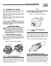
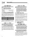
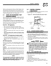
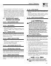
2.7 GROUNDING THE GENERATOR
The National Electrical Code requires the frame and
external electrically conductive parts of this equip-
ment to be properly connected to an approved earth
ground and/or grounding rods. For that purpose, a
GROUND LUG (Figure 2.2) is provided on the gener-
ator mounting base. Consult a qualified electrician
for grounding requirements in the area. Grounding
procedures must meet local regulations.
Do not connect the ground wire to any pipe
that carries a flammable or explosive substance
– FIRE or an EXPLOSION may result.
Proper grounding helps protect personnel against
electrical shock in the event of a ground fault condi-
tion in the generator or in connected electrical
devices. In addition, grounding helps dissipate static
electricity that often builds up in ungrounded
devices.
Figure 2.2 – Generator Grounding Lug (typical)
2.8 GENERATOR AC NEUTRAL
CONNECTIONS
The manufacturer uses an UNGROUNDED AC neu-
tral. Grounding is recommended only at the main
service entrance. If the neutral wire is grounded and
one of the phase loads becomes grounded, the exces-
sive current opens the load circuit breaker or col-
lapses the generator field. The actual result depends
on the electrical characteristics of the particular
installed generator.
Failure to connect the generator neutral prop-
erly will result in unbalanced line-to-neutral
voltages. Resulting high voltages will cause
equipment damage.
!
G
R
OU
NDIN
G
L
UG
DANGER
Section 2 — Installation
40kW Liquid-cooled Generators