


9 -35
gravity. Before reinstalling the battery in the spring, it
should always be fully recharged.
9.5 SWITCHES
Switches either open a circuit to stop current flow or
close and allow current to flow through.
A normally open (N.O.) switch prevents current flow
until the switch is actuated, completing the circuit and
allowing current to flow through it. An example is a light
switch - the lights are off until the switch is actuated
and the lights go on.
A normally closed (N.C.) switch allows current to flow
until the switch is actuated, breaking the circuit and
stopping current flow through it. An example is an
ignition switch that grounds the magneto when in the
off position (completing the circuit) but opens the circuit
when in the ON position allowing the engine to operate.
Switches are selected with regard to Current rating
(contacts must be of sufficient size to carry the required
current), Voltage rating (switches insulated for specific
voltages), Case or housing (switches that are exposed
to moisture and must be sealed to prevent moisture
from entering), and Actuating type (push, pull, rotary,
momentary contact, or micro switches).
NOTE:
Check that the connections to the switches are
secure and that a switch is being activated properly
before performing electrical test on switches. (Safety
switches on speed selector and clutch levers may be
out of adjustment and not activating.)
IMPORTANT:
When checking switches, remove them
from their respective circuit by disconnecting the wires
from the switch at the connector(s). Damage could
result to the meter or machine components if switches
are left in.
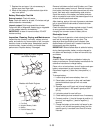
Normally Open Switch
To test a normally open switch (key, headlight, safety,
or seat) connect the ohmmeter across the switch
terminals. Meter should indicate open circuit (infinite
resistance). Activate the switch. The ohmmeter should
read up scale to zero resistance (Close Circuit). This
indicates the switch is operating properly. Also check
from each terminal to the switch case (if case is metal).
Reading should show infinite resistance indicating no
short to ground.
Variation from test results described indicates a
defective switch.
Normally Closed Switch
To test a normally closed switch connect the ohmmeter
across the switch terminals. Meter should indicate a
closed circuit (zero resistance). Activate the switch and
the meter should move to open circuit (infinite
resistance). Check from each terminal to ground
(switch case). Meter should show open circuit (infinite
resistance).
Variation from test results described indicates a
defective switch.
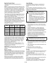
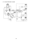
Ignition Switch
NOTE:
Refer to the wiring diagram of the unit involved
to determine switch functions and test using the
methods described.
The ignition switch incorporates a number of functions,
although not all functions are used on all equipment.
The switch has three positions: OFF, RUN, and a
momentary contact START position. Use an ohmmeter
to check the continuity of the switch in each position.
OFF Position
- Should be continuity between contacts
G and M. These connections ground the engine
magneto and stop the engine in the OFF position.
RUN Position
- Should be continuity between contacts
B and A. These connections supply power to the rest of
the wiring harness. Connections G and M open to each
other.
START Position
- Hold switch in START position while
testing. There should be continuity between contacts
S1 and S2. These connections apply power to close
the solenoid contacts and operate the starter motor.
In addition to the above test, place the switch in the run
position and check between each contact and ground
(metal case) to be sure no terminals are grounded. If
the switch is operating properly, there will be no
continuity between contacts other than those
described.
9.6 SOLENOID AND RELAYS
Solenoid and relays are both magnetically operated
devices. Both devices operate on the principle that
passing a current of electricity through a coil of wire will
create a magnetic field strong enough to attract a piece
of iron or steel. Each device uses this principle in a
slightly different manner.
Relay
- A basic relay consists of a coil of wire wound
around a soft iron (magnetic) core. When current is
passed through the coil, the core is magnetized and
pulls down on a magnetic lever. The lever in turn is
attached to several switch contacts which open or
close other electrical circuits. In this fashion, a small
current can control one or more larger electrical
currents and actuate several other devices. In most
cases a relay contact moves only a fraction of an inch
and the magnetic pull is small.
Solenoid
- A basic solenoid consists of a coil of wire
wound around a hollow tube. A magnetic core slides
inside the tube. When current is passed through the
coil, the core is pulled into the solenoid with
considerable force. With proper design, a solenoid can
exert considerable force over a distance of several
inches. A solenoid can therefore, pull a lever, close a
heavy contact, or perform other jobs that require a
straight line pull.