


7 -24
Before assuming that internal transmission problems
exist, check all external linkage. Inspect the shifting
linkage beginning with the control lever and work
towards the transmission. Check for binding. Look for
broken or missing cotter pins and sheared keys.
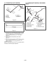
7.2 CLUTCH ADJUSTMENT
Clutch adjustment is necessary anytime clutch
slippage occurs.
Clutch rods when engaged should just completely
compress the springs on the clutch actuating lever
when fully engaged.
To adjust, tighten the jam nuts until proper adjustment
is obtained.
If external adjustments do not correct problems,
internal examination may be necessary.
7.3 TRANSMISSION REMOVAL
1. Remove engine from tractor.
2. Remove battery.
3. Remove capscrews holding the handles, fuel tank,
and battery box assembly to the chassis, and lift
assembly off chassis.
4. Remove wheels and wheel hubs.
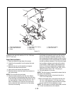
7.4 FORWARD-REVERSE CLUTCH &
PLANETARY SYSTEM
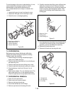
To gain access to the forward-reverse clutch and
planetary system, remove advance housing and rotate
actuating rod with the lever until entire planetary
system is released. All components of the forward-
reverse clutch assembly are now ready for inspection.
1. Examine all parts for excessive wear or play.
2. Pay particular attention to the orbit gears and the
orbit gear pins. If the bores of the gears are scored
or out-of-round, replace gears and pins.
3. Check internal gear teeth for wear.
4. If friction surface of clutch cup is worn or damaged,
replace cup.
5. Check the friction surfaces of the reverse cone and
internal gear for scoring. If surfaces are damaged,
replace parts to prevent rapid wear of a new clutch.
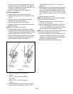
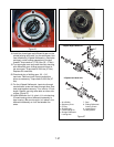
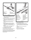
When replacing the forward-reverse clutch unit, the
planetary gears must be timed.
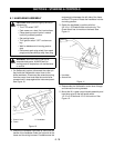
Time planetary gears as follows:
1. Place sun pinion in bore of front pin plate.
2. Secure pin-plate quill to the pin plate with three
quill-securing bolts.
3. Place the orbit gear pins in orbit gears.
4. Mesh the three gears with sun pinion so that the
timing marks form an equal sided triangle. Timing
marks (Figure 19) are white paint marks on the
opposite side of gears.
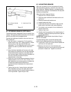
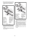
When replacing this unit in the transmission it is
necessary to mesh the teeth on the actuating rod and
the clutch slide rods (Figure 19) to accept the
assembly.
7.5 FIRST -SECOND GEAR, CLUTCH AND
PLANETARY
To examine the first-second clutch and planetary,
remove engine and release unit by turning the
actuating shaft.
Figure 18
Timing Marks
Figure 19
1
2
3
4
5
6
7
8
9
10
11
12
13
14
15
16
1. Bearing Nut
2. Compression Spring
3. Front Pin Plate
4. Sun Pinion Spur Gear
5. Quill and Bushing
Assembly
6. Orbit Spur Gear
7. Forward-Reverse Orbit
Gear Steel Pin
8. Spacer
9. Reverse Idler Spur
Gear
10.Front Pin Spacer
11.Friction Disk
12.Reverse Gear Cone
13.Clutch Cup Assembly
14.Right hand Clutch Slide
Rod
15.Internal Spur
16.Gear Cup