


EN - 28
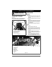
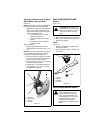
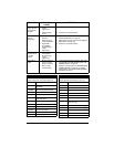
ADJUSTING STEERING LEVERS
(Figure 21)
IMPORTANT: Adjust each steering lever
equally.
NOTE: When adjusting steering levers for the
first time it is recommended that you make
adjustments in the following order.
1. Adjust Steering Lever Height
1. Remove mounting hardware that
attaches the handlebars to the upper
control arm. Move handlebar up or down
until the handlebar mounting holes are
aligned with the prefered adjustment
holes.
2. Install mounting hardware and tighten.
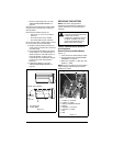
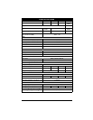
2. Adjust Steering Lever Width
1. Loosen hardware at the base of the
lower control arm item 5.
2. Rotate eccentric spacer to move the
levers away from or closer to the
operators position (figure 22).
3. Tighten hardware.
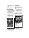
3. Adjust Steering Lever Forward or
Backward
1. Loosen, do not remove, the bolts
securing the handlebar to the upper
control arm.
2. Rotate steering lever forward or
backward to desired position and tighten
bolts.
NOTE: Tighten upper bolt first.
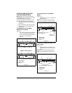
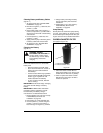
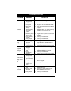
Forward Speed Adjustment
(Figure 23)
NOTE: Reverse speed cannot be adjusted. If
unit tracks excessively left or right in reverse,
see your dealer for repair.
IMPORTANT: The unit should track within
2 feet (0.61 m) of a straight line for 30 feet
(9.14 m).
The travel of the steering levers may need
adjustment if the unit turns to the right or left
when both steering levers are pushed as far
forward as possible.
NOTE: The side the unit turns toward
indicates that the drive wheel on that side is
turning slower than the opposite drive wheel.
Either the wheel that is turning faster needs
to slow down or the wheel that is turning
slower needs to speed up to allow the unit to
travel in a straight line.
1. Determine which way the unit turns.
2. Loosen jam nut on the adjustment bolt.
3. Adjust speed by:
• Turning adjustment bolt clockwise to
decrease steering lever travel.
• Turning adjustment bolt
counterclockwise to increase steering
lever travel.
4. Tighten the jam nut.
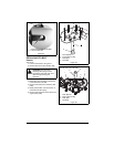
Figure 21
2
1
1. Handlebar
2. Upper Control Arm
3. Adjustment Holes
4. Eccentric Spacer
5. Mounting Hardware
6. Lower Control Arm
5
Adjustment 2
Adjustment 1
Adjustment 3
4
6
3
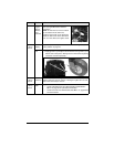
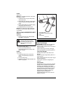
Figure 22
Rotate this end away from the operator
position to move the steering levers out.
Rotate this end away from the operator
position to move the steering levers in.