


EN - 26
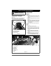
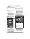
4. Remove nut and bolt securing battery
hold down bracket. Save for
reinstallation.
NOTE: The bolt securing the battery is
mounted through the underside of the frame.
Place hand beneath frame to catch loose
bolt.
5. Remove battery from unit.
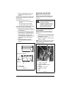
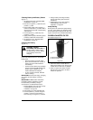
Install Factory-Installed Battery
(Figure 17)
1. Tip seat forward. See “TIPPING SEAT
FORWARD” on page 22.
2. Set battery inside the frame, underneath
the seat with battery terminals
positioned as shown (Figure 17).
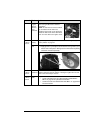
3. Place battery hold down bracket on top
of the battery. Hook the curved end of
the bracket in the lower mounting hole in
the wall of the frame (Figure 18).
4. Position bolt through the mounting hole
nearest to the battery and through
mounting bracket. Secure with nut.
IMPORTANT: Tighten nut until battery is
secure and will not move or rattle during
operation. DO NOT overtighten.
5. Connect positive (+) cable first, then
negative (–) cable.
6. Apply petroleum jelly or dielectric grease
to battery cable ends and terminals.
7. Tip seat back. See “TIPPING SEAT
FORWARD” on page 22.
U1 Battery Installation
(Figures 18 and 19)
1. Remove factory battery. See “Remove
Factory-Installed Battery” on page 25.
NOTE: Be sure to cut cable tie connecting
positive battery cable to battery hold down
bracket.
2. Set battery inside the frame, underneath
the seat with terminals positioned as
shown (Figure 19).
3. Place battery hold down bracket on top
of the battery. Attach the curved end of
the bracket in the upper mounting hole
in the wall of the frame (Figure 18).
4. Position bolt through the mounting hole
nearest to the battery and through
mounting bracket. Secure with nut.
IMPORTANT: Tighten nut until battery is
secure and will not move or rattle in the
frame.
5. Connect positive (+) cable first, then
negative (–) cable.
6. Apply petroleum jelly or dielectric grease
to battery cable ends and terminals.
7. Tip seat back. See “TIPPING SEAT
FORWARD” on page 22.
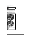
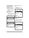
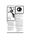
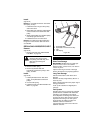
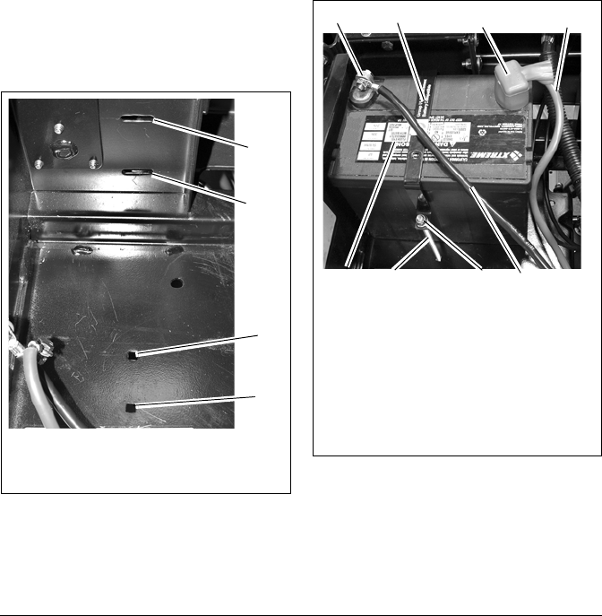
Figure 18
1. Factory Battery Mounting Hole
2. U1 Battery Mounting Hole
1
2
1
2
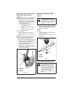
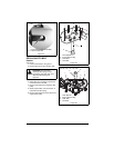
Figure 19
1. Positive (+) Terminal
2. Positive (+) Cable
3. Battery Hold-Down Bracket
4. Battery
5. Negative (–) Terminal
6. Negative (–) Cable
7. Nut
8. Bolt
3
5
1
2
4
6
7
8