


Installation
6 312585E
Installation
The Graco warranty will not apply if cleaning solutions
other than those recommended by Graco are used in
these units. Only use solutions that are not harmful to
the wetted parts. See the Technical Data in the displace-
ment pump manuals 311825, 311827, and 312745.
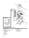
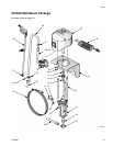
See F
IG. 1. Connect the suction hose (P) between the
pump fluid inlet and the suction tube (R), using thread
sealant on the male threads. Screw on the suction tube
strainer. Place the suction tube in the supply drum, and
adjust it so it is 1 in. (25 mm) off the bottom of the drum.
Tighten the thumbscrew of the pipe hanger onto the
drum.
Connect the spray hose (S) to the pump outlet manifold.
For two gun spraying, remove the plug in the manifold
and connect another spray hose. Connect the spray gun
(T) to the hose (S). Use thread sealant on the male
threads.
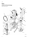
Wall Mount Packages
1. Ensure the wall is strong enough to support the
weight of the pump assembly and accessories, fluid,
hoses, and stress caused during pump operation.
2. Ensure that the mounting location has sufficient
clearance for easy operator access.
3. Position the wall bracket at a convenient height,
ensuring that there is sufficient clearance for the
fluid suction line and for servicing the displacement
pump.
4. Drill four 7/16 in. (11 mm) holes using the bracket as
a template. Use any of the three mounting hole
groupings in the bracket. See Wall Mounting
Bracket Diagram, page 20.
5. Bolt the bracket securely to the wall using bolts and
washers designed to hold in the wall’s construction.
6. Attach the pump assembly to the mounting bracket.
7. Connect air and fluid hoses.
Flush Before Using Equipment
The equipment was tested with lightweight oil, which is
left in the fluid passages to protect parts. To avoid con-
taminating your fluid with oil, flush the equipment with a
compatible solvent before using the equipment. See
your respective pump manual. See Related Manuals on
page 3.
Integrated Air Control Module
See FIG. 1. The integrated air control module (C) is
included with all packages. It includes the following (see
311239 for detailed information):
• Bleed-type master air valve (D): required in your
system to relieve air trapped between it and the air
motor when the valve is closed.
• Pump air regulator (E): adjusts air pressure to the
motor and fluid outlet pressure of pump. View the
gauge (F) to read air pressure.
• Safety relief valve (G): automatically opens to
relieve air pressure, to prevent pump overpressur-
ization.
• Air filter (H): removes harmful contaminants from
entering the air control module and air motor.
Trapped air can cause the pump to cycle unexpectedly,
which could result in serious injury from splashing or
moving parts.