


19
28
f3
14
5
A
15
L19
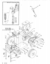
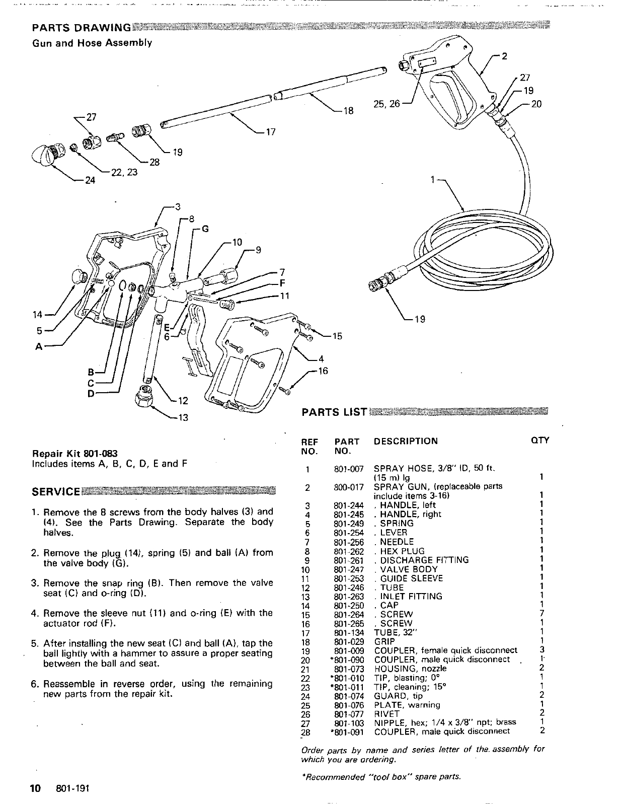
REF PART DESCRIPTION
QTY
Repair
Kit
801-083
NO. NO.
Includes items
A,
6,
C.
D,
E
and
F
(15
ml
lg 1
SERVICE
include items 3-16) 1
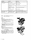
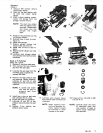
1.
Remove the
8
screws from
the
body halves
(3)
and
3 801-244
.
HANDLE, left 1
(4).
See
the
Parts Drawing. Separate
the
body
4
801-245
.
HANDLE, right 1
5
801-249
.
SPRING 1
halves.
6
801-254
.
LEVER 1
7
801-256
.
NEEDLE 1
1
9 801-261
.
DISCHARGE FlTlNG 1
1
3.
Remove the snap ring
(61.
Then remove the valve
12
801-246
,
TUBE
1
1
4. Remove the sleeve nut
(11)
and
O-ring
(E)
with
the
14 801-250
.
CAP
15 801.264
.
SCREW
1
actuator rod
(F).
16 801-265
.
SCREW
7
1
17 801.134 TUBE.
32"
1
1
ball lightly
with
a hammer
to
assure a proper seating 19 801-009 COUPLER, female quick disconnect 3
between the ball and seat.
20
'801-090 COUPLER, male quick disconnect
.
1.
22
'801-010 TIP, blasting;
0"
1
1
2
25 801-076
PLATE, warning
26 801-077 RIVET
1
2
27 801-103 NIPPLE, hex; 1/4
x
3/8"
npt; brass 1
28 '801-091 COUPLER, male quick disconnect 2
1 801-007 SPRAY HOSE,
3/8"
ID,
50
ft.
2
800-017 SPRAY GUN, (replaceable parts
2.
Remove the
plug
(141. spring
(5)
and
ball
(AI from
8
801-262
.
HEX PLUG
the
valve body
IG).
10 801-247
.
VALVE BODY
11 801-253
.
GUIDE SLEEVE 1
seat
IC1
and
O-ring
(Dl.
13 801-263
.
INLET FITTING
5.
After installing the
new
seat
(Cl
and
ball
(A),
tap
the
18 801-029 GRIP
21 801-073 HOUSING, nozzle
2
6.
Reassemble
in
reverse order, using the remaining
23
.801.011
TIP,
cleaning;
150
new
parts from
the
repair
kit.
24
801-074 GUARD, tip
Order parts
by
name and series letrer
of
the. assembly
for
which
you
are ordering.
'Recommended "tool
box"
spare
parts.
10
801-191