


All controls are shipped with the output voltage set to the industry standard 24VAC. To use the GL-235
with older 12VAC valves, move jumper J4, located on the right side of the circuit board.
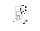
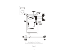
The GL-235 provides two different types of connections to the pool/spa actuators. For older actuators with
no wire end connector, a 3 position terminal block is used. Connect the wires to the proper terminal block
according to the color code shown in Figure 4. If the valve operates opposite to the way it is supposed to,
reverse the red and white wires. Be careful not to short the valve output wiring. The GL-235 is fused and
shorting the output will require replacing the fuse.
For newer Goldline, Compool, Hayward, and Jandy actuators (with wire end connectors), two 3-pin
connectors are supplied. Plug the actuator into one of the two 3 pin connectors as shown in figures 2 or
3. If the valve operates opposite to the way it is supposed to, disconnect and plug into the other connector.
High Voltage (HV) output: Booster Pump
The GL-235 can control a high voltage booster pump in addition to the normal low voltage solar valve. Note
the high voltage relay contacts are isolated so that the booster pump can be run on a separate circuit, as
required by many local codes. The GL-235 turns on, the valve output will operate first, and then the HV
relay will operate 30 seconds later.
High Voltage (HV) output: Timeclock Override
The GL-235 can also be used to override the filter pump timer. This is very important if recirculate freeze
protection or nocturnal cooling functions are being used. Also, this function can be used on systems where
the system should operate whenever solar heat is available, regardless of the timer settings. The HV relay
will operate approximately 30 seconds after the LV relay.
Sensor Mounting and Wiring
Most installations use a PC sensor to measure the pool temperature and another PC sensor to measure the
solar temperature. Alternatively, an SC-¼ sensor can be screwed into the pump strainer basket to measure
the pool temperature.
Pool Sensor: Drill a 3/8” (or 5/16”) hole in the PVC pipe. Remove burrs around the hole. Check that the
O-ring is seated on the PC sensor and then insert sensor into pipe. Tighten hose clamp over the sensor to
make a seal—DO NOT OVERTIGHTEN.
Solar Sensor: Use a screw or silicon adhesive to attach the sensor near the solar collector array. The sensor
does not have to be attached to the collectors. It is only important that the sensor be exposed to the same
sunlight as the collectors. Additionally, the underside of the sensing element may be covered with silicon
to minimize wind cooling.
Other 10K ohm Goldline sensors may be substituted. Wire should be twisted pair 20AWG. Sensor wiring
run outdoors must be rated for outdoor use and ensure that the wire connections are protected from the
weather. Do NOT run sensor wires in the same conduit or multiconductor cable as the valve actua-
tor wires or any 120/240V circuit. For long runs or runs near other electrical wiring use shielded cable
(Belden 8428 for outdoor use). Ground the shields to the GL-35/LV ground screw.
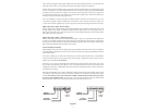
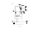
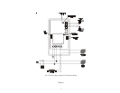
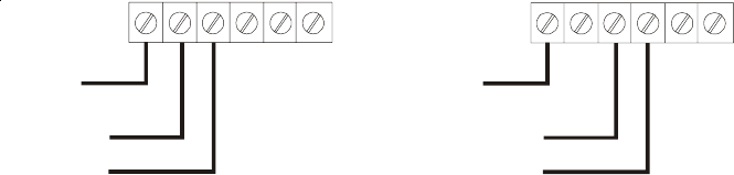
240 VAC
input power
115 VAC
input power
EARTH
GROUND
EARTH
GROUND
{
{
high
voltage
output
high
volta
g
e
output
Figure 1
3