


10
GP7122 REPAIR INSTRUCTIONS
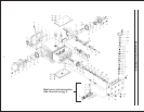
TO ASSEMBLE VALVE CASING
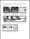
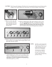
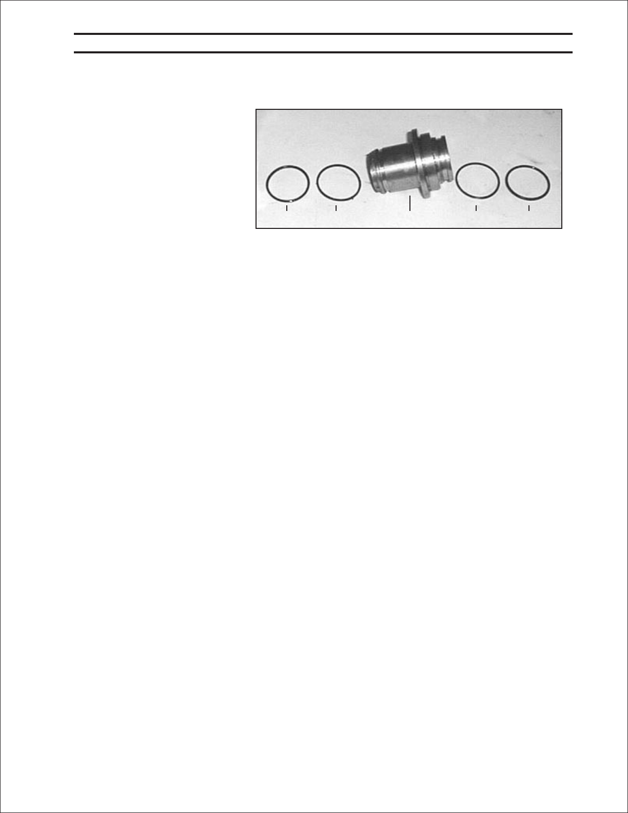
18. Check O-rings (39A) and
support rings (39B) on seal
case (39). Clean surfaces of
seal sleeves (38) in crankcase
(1) and sealing surfaces of
valve casing (50). Insert seal
sleeve with plunger into
crankcase guide. Turn crank-
shaft to (22) until plunger with
crosshead (25) pushes against
plunger tighten plunger (36) to
26 ft-lbs.
19. Push valve casing carefully over O-rings of seal case and centering studs (50A). Tighten nuts (49A) to space
103 ft-lbs.
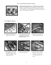
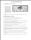
TO DISASSEMBLE GEAR END
20. Take out plunger (36) and seal sleeves (38) as described above. Drain oil.
21. After removing the circlip ring (33B), pry out seal adapter (33) with a screw driver
22. Check seals (32,32A,33A) and surfaces of plunger base (25).
23. Remove crankcase cover (4). Loosen inner hexagon screws (24A) on the connecting rods (24) and push
con rod halves as far into the crosshead guide as possible.
CAUTION: Connecting rods (24) are marked for identification. Do not twist connecting rod halves.
Connecting rod is to be reinstalled in the same position on crankshaft journals.
24. Check surfaces of the connecting rod (24) and crankshaft (22).
25. Take out bearing cover (14) to one side and push out crankshaft (22) taking particular care that the
connecting rod (24) doesn't bend.
CAUTION: Ring (32A) must always be installed so that the seal-lip on the inside diameter faces the oil.
26. Reassemble in reverse order: Regulate axial bearing clearance - minimum 0.1mm, maximum 0.15mm-by
means of fitting disc (20A). The crankshaft (22) should turn easily with little clearance. Tighten inner
hexagon screws (24A) to 30 ft.-lbs.
CAUTION: Connecting rod (24) has to be able to be slightly moved sidewise at the stroke journals.
27. Reassemble cover (4) and seal (5) onto crankcase (1). Fasten with hexagon screws (10).
28. Reinstall shim (33C), and seal adaptor (33) with radial shaft seal (32), ring (32A) and o-ring (33A) onto
crankcase (1).
29. Reinstall remainder of fluid end as described above in “To Assemble Valve Casing” section (21 and 22
above).
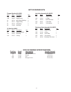
39A 39B 39 39B 39A