


INSTALLATION
Note:
LAWN MASTER
is for indoor installation only. Do not plug transformer into the
same outlet as other high power devices such as garage door opener, power tools, etc.
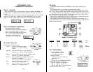
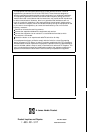
Select an indoor location near a 1
10
volt outlet to mount your controller. Avoid
using an outlet that is controlled with an on/off switch. Mount approximately 48”
from floor.
Controller should not be exposed to water or operated at temperatures below 14 deg.
or above 113 deg. Fahrenheit.
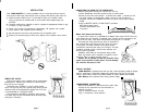
Screw a No. 8 screw into wall leaving approximately
1/8”
exposed. Use a plastic
anchor sleeve if wall is plaster board or masonry.
Slip the keyhole in the back of the controller over the exposed screw.
Screw No. 8 screws through the holes at the bottom of the controller case to secure.
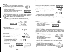
WIRING THE VALVES
Connect your valves to the controller with 20 gauge plastic
jacketed wire. If distance from controller to valves is longer
than 700 feet use 16 gauge.
Thermostat wire is available in 4 and 7 strand colored
wires. You may bury wire in the ground being careful to avoid
locations which can be disturbed by digging. Use of UF wire
is recommended for underground wiring.
Extra protection is possible by pulling the wires through
PVC water pipe. All wire connections should be made using
water-proof connectors.
page
2
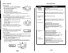
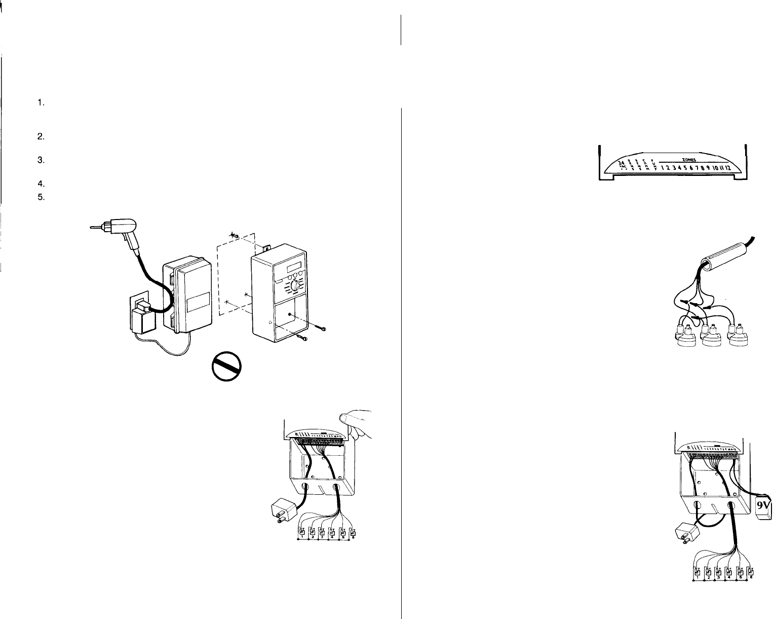
CONNECTING THE WIRES TO THE CONTROLLER
l
Remove lower panel covering, turn up and over. Line up
terminal identification area with terminal screws as shown below.
l
Connect the wire from valve number 1 to terminal slot number
1,
connect the wire
from valve number 2 to terminal slot number 2 and so on until all valves are
connected. Connect the COMMON wire from the valves to the terminal marked
COMM.
l
If using a MASTER VALVE or PUMP START, see below.
-Back side of lower panel
-Terminal identification area
I
-
-
I
-Terminals
Master Valve Pump Start Hook-Up
In cases where a pump is to controlled by the Master Valve output, DO NOT drive the
pump directly from the controller. The Master Valve Terminal must be connected to the
coil of a 24 VAC relay. (Lawn Genie Pump Relays are relay part no.
L3OOOOW)
The pump latch relay should be set up by an electrician so
that a switch closure will activate the latch relay coil, turning
on the pump. The switch contacts of the relay should be
connected to control the latch relay coil, see figure. The relay
should be mounted at least 5 feet from the controller, and
the box must be grounded.
Installation must follow all local electrical wiring codes.
Make sure master valve is selected as needed in all your
programs. Refer to watering duration (page 5)
Caution: Do not attempt to power the controller using
power from one phase of pump power. This will damage
the controller, the pump or both.
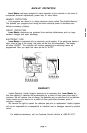
INSTALL BATTERY
LAWN MASTER
is protected from time loss with a back-up battery (install the battery
after the transformer is connected.) Battery will maintain time and day up to 60 days
during a power failure. Install 9 volt alkaline battery as shown. (Battery not included).
Note: Battery
will not operate valves during a power outage.
I
I
TRANSFORMER CONNECTION
Make sure transformer is disconnected from power outlet.
Connect the two lead wires from the transformer to
terminals as shown.
l
First (2) terminal locations: 24 VAC
l
Plug- in transformer, check operation.
page
3