


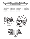

CONTROLS AND INSTRUMENTS
SWAY
CONTROL
C
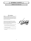
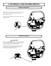
WARNING
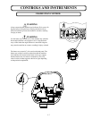
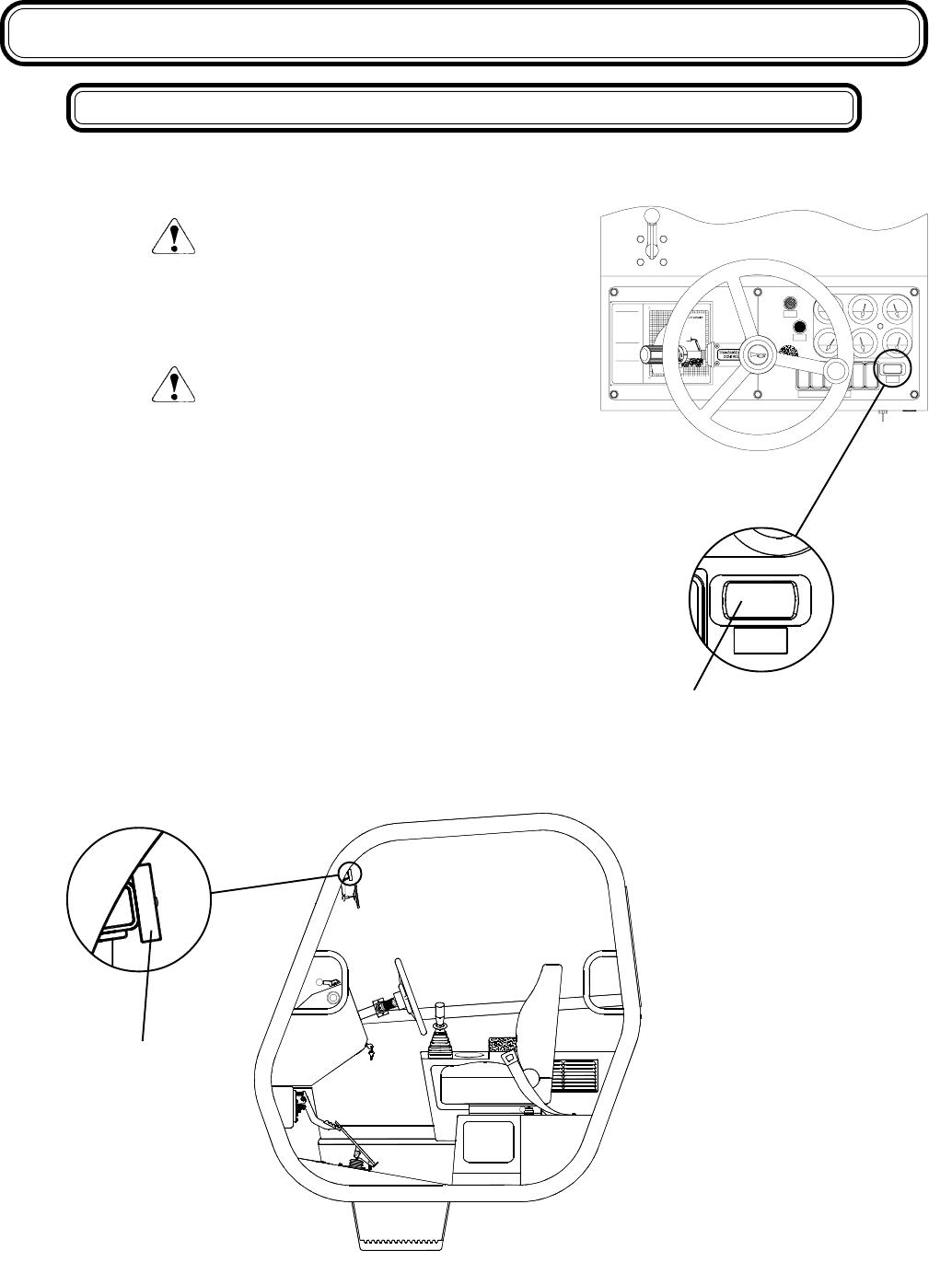
Always ensure that the machine level indicator (D) is at zero (0)
degrees before raising the boom. Raising the boom with an
unlevel machine may cause the machine to overturn, resulting
in injury or death.
WARNING
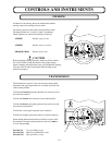
Use the frame sway control to level the machine only when the
boom angle indicator is at 0 degrees or less. Using the frame
sway control when the angle indicator is more than 0 degrees
may cause the machine to overturn, resulting in injury or death.
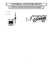
The frame sway control (C) is located on the dash panel. The
frame sway control is used in conjunction with the machine
level indicator (D) located in the center of the cross support
that the interior rear view mirror is mounted on. The sway
control switch is either toggled to the left or right depending
on the particular requirement.
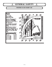
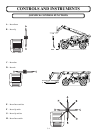
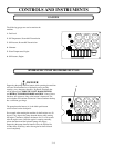
BRAKE ON
(C) LETTER VISIBLE = 3,000 LBS
(D) LETTER VISIBLE = 2,000 LBS
P/N 3-1483
0
(1.22)
METER
FEET
(6.10)
28
(8.54)
24
(7.32)
20
4
455 NORTH SUPERI OR AVENUE
MACHINE ON A FIRM, LEVE L
SURFACE WITH UND AMAGED,
PROPERLY I N FLATE D CALCIU M
CAPACITY IS PER ANSI B56.6
LOAD L IMIT S / HOR IZO NTAL BOOM
(B) LETTER VISIBLE = 4,000 LBS
OR OPTIO NAL FO AM FI LLE D TI RES.
CHLORIDE SOLUTION FILLED TIRES
RATED LIFT CAPACITIES ARE WITH :
LAST FULLY VISIBLE LETTER
(A) LETTER VISIBLE = 6,000 LBS
RETRACTED = 8,000 LBS
REAR AXLE LOCK-UP EN GAGED.
(.61 METERS) LOAD CENTER WITH
MANUFACTURER'S RECOMMENDED
STABILI TY T ES TS USI N G S TANDAR D
(1.22x1.22x1.22 METERS). LOAD
HOMOGENEOUS CUBES 4x4x4 FT.
P.O. BOX 790
PHONE 906-353-6675
FAX 906-353-7543
CAPACITIES AT 24 INCH
STANDARD FO RK FRA ME.
BARAGA, M ICHI GAN 49908
12
(3.66)
16
(14.64)
48
METER
FEET
(6.10)
28
(8.54)
24
(7.32)
20
32
20
24
(7.32)
(8.54)
28
(9.76)
44
(13.42)
40
36
(10.98)
(12.20)
0
(4.88)
(4.88)
12
(3.66)
816
(6.10)
204
(1.22)(2.44)
(4.88)
12
(3.66)
16
(6.10)
20
SWAY
CONTROL
HEATERHEADLIGHT
LICS
RY
PUMP OFF
FRAME SWAY CONTROL
D
3 - 7