


32
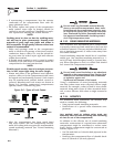
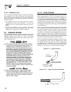
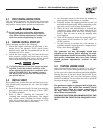
2.7.3 BATTERY CABLE CONNECTIONS
1. Connect the battery cable from the battery post or
terminal indicated by a POSITIVE, POS or (+) to
the lug on the starter contactor (Figure 2.16).
NOTE:
Check to be sure the battery cable boot for the
starter cable has been installed.
2. Connect the battery cable from the battery post
indicated by a NEGATIVE, NEG or (-) to the
frame ground connection (Figure 2.16).
3. Connect cables so the connectors are clean and
tight.
Figure 2.16 – Connecting Battery Cables
NEG
FUEL
POS
2.7.4 BATTERY COMPARTMENT
Install the generator battery in its own, vented com-
partment. Place the battery compartment away from
any source of heat, sparks or flame.
Provide ventilation openings in the battery compart-
ment. The minimum size of openings should be 2
square inches at the top of the compartment. Mount
the battery on a strong, rigid supporting structure,
where leaks and spills of battery fluid will not cause
damage.
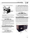
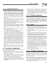
2.8 OPTIONAL ACCESSORIES
A plug-in receptacle (Figure 2.17) is provided on
the generator set. Use this receptacle to connect an
optional remote-mounted start/stop panel to the
generator. Installation of such a panel will permit
starting and stopping the generator engine from any
convenient location inside the vehicle.
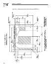
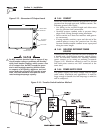
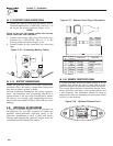
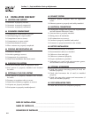
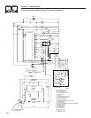
Figure 2.17 – Remote Panel Plug-in Receptacle
12.00"
14
0
17
1
5
1
8
14A
1
3
2
5
4
6
0
14
17
1
8
14A
1
5
1
5
17
14A
1
8
14
0
N
o.
WIRE
WIRE
CO
L
OR
RED
YELL
OW
O
RAN
GE
WHITE
BL
UE
BR
O
W
N
12.0
(
305
)
LENGTH
(
mm
)
12.0
(
305
)
12.0
(
305
)
12.0
(
305
)
12.0
(
305
)
12.0
(
305
)
FUNCTION
GROUND
ENGINE RUN SIGNAL
12 VDC
START
STOP
PRIME
P
/
N:
0
D
9099
-
B
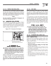
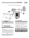
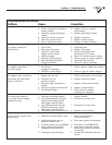
2.8.1 REMOTE START/STOP PANEL
A remote mounted Start/Stop panel (Figure 2.18) is
available that allows the user to start and stop the
generator engine conveniently from inside the vehicle.
The remote panel includes a Start/Stop switch, hour-
meter, generator run lamp, a fuel prime switch, and
a wire harness. The hourmeter should be used in
conjunction with the maintenance operations found
in Part I of this manual.
Figure 2.18 – Optional Remote Panel
PRIME
F
U
E
L
S
T
OP
R
UN
Section 2 – Installation
Recreational Vehicle Generator