


30
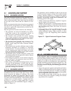
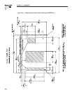
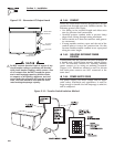
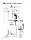
Figure 2.13 – Generator AC Output Leads
483.1
AC OUTPUT
HARNESS
REMOTE PANEL
CONNECTOR
BATTERY
CONNECTIONS
FUEL FILTER
I
t
r
e
,
e
h
i
t
w
a
n
c
.
-
s
m
,
I
e
W
W
y
s
S
r
o
P
w
e
A
C
N
R
E
G
E
t
TM
Do NOT connect electrical loads in excess of any
circuit breaker rating or problems will develop
with circuit breaker tripping, which causes a loss
of AC output. Also, do NOT exceed the gener-
ator's rated wattage capacity. Add the watts
or amperes of all lighting, appliance, tool and
motor loads the generator will operate at one
time. This total should be less than the unit's
rated wattage/amperage capacity.
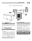
2.6.4 CONDUIT
Route the connections between the generator and the
junction box through approved, flexible conduit. The
following general rules apply:
Cut wiring to the required length and allow extra
wire for junction box connections.
Carefully prepare conduit ends to prevent sharp
edges from cutting through wiring insulation.
Route conduit so it does not interfere with genera-
tor movement.
If using metallic conduit, vapor seal the end of the
conduit where it enters the junction box. Do this
because flexible metallic conduit is not vaporproof
along its entire length.
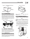
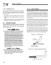
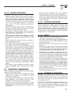
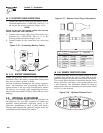
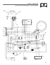
2.6.5 ISOLATING DIFFERENT POWER
SOURCES
Connections from the junction box must terminate in
a double-pole, double-throw transfer switch (Figure
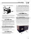
2.14). An alternate method for isolating different
power sources is by using an isolating receptacle
(Figure 2.15). Whichever method is used, be certain
that both power sources are NOT connected at the
same time.
2.6.6 POWER SUPPLY CORD
The power supply cord must comply with all appli-
cable codes, standards and regulations. It must be
large enough to handle the full amperage to which it
will be subjected.
•
•
•
•
Section 2 – Installation
Recreational Vehicle Generator
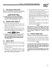
Figure 2.14 – Transfer Switch Isolation Method