


Section 1.3
OPERATIONAL ANALYSIS
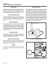
GENERAL
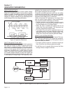
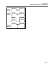
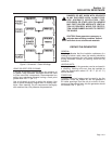
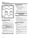
Figure 1, below, is a block diagram of the Impact Plus
computer controlled RV generator. The diagram is
Intended only for the purpose of illustrating generator
operation. Refer to the actual wiring diagram for
wiring interconnections.
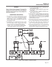
OPERATIONAL DESCRIPTION
1. The Impact Plus is a computer controlled generator that uses
an inverter to create a superior sine wave and maintain a
steady frequency of 60 Hz. The PERMANENT MAGNET
ROTOR is directly coupled to the ENGINE and rotates at the
same speed as the engine.
2. As the ROTOR turns, its magnetic field cuts across a number
of STATOR windings, to induce a voltage into those windings.
A voltage is induced into the following STATOR windings:
a.Phase 1 and 2 of the STATOR POWER WIND-
INGS (output leads AC1-AC2 and SL1-SL2).
b.The STATOR POWER SUPPLY WINDING with
output leads PS1-PS2.
c. The STATOR TIMING WINDING (output leads
TIM1-TIM2).
d.STATOR BATTERY CHARGE WINDING with
output leads 55, 66 and 77.
3. STATOR BATTERY CHARGE WINDING output is delivered to
the unit battery via a BATTERY CHARGE RECTIFIER (BCR)
and a 1 OHM, 50 WATT RESISTOR. The circuit is completed
through the battery to frame ground and back to the BATTERY
CHARGE WINDING via Wire 55.
4. Stator timing winding output is delivered to the A6060 circuit
board. The timing winding output is used to determine engine rpm.
5. The stator power supply winding output is delivered to the
inverter. This is the power supply for operation of the inverter.
6. Stator power winding output (phase 1 and 2) is delivered to two
separate bridge rectifiers, where it is rectified to DC. This
becomes the DC link voltage and is delivered to the inverter.
Page 1.3-1
Figure 1. Block Diagram- A Generator System