


Section 7.2
ENGINE DC CONTROL SYSTEM / AC TROUBLESHOOTING
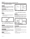
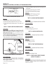
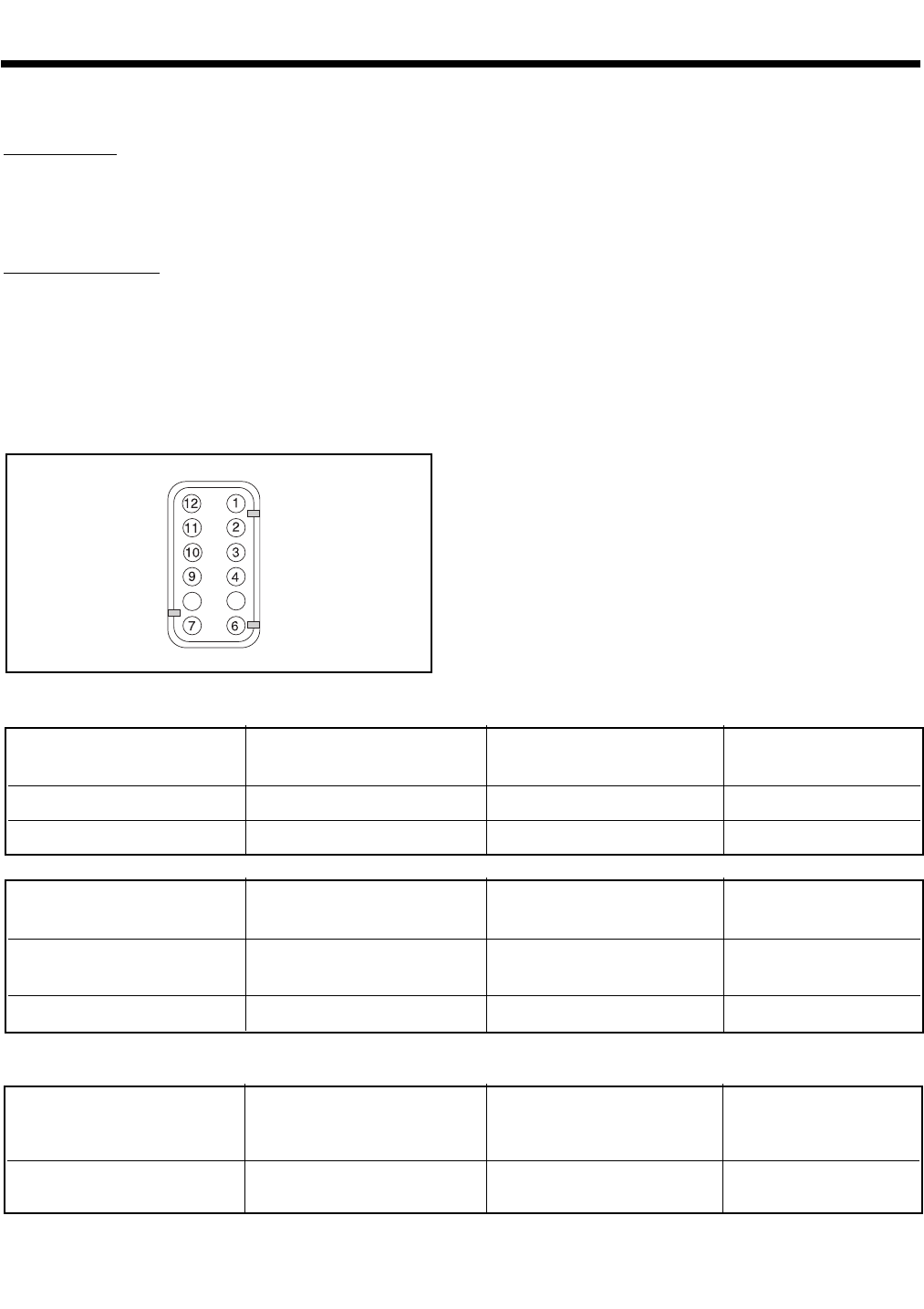
TEST 31 - STATIC TESTS ON INVERTER
ASSUMPTION:
• Inverter not connected to generator.
• Inverter has been disconnected for at least 5 min-
utes from running genset to allow capacitors to dis-
charge.
TEST PROCEDURE:
1. Set a DVOM to DIODE RANGE. Measure the 12 position con-
nector on the inverter according to the chart below. Connect
the negative and positive test leads as indicated in the chart.
2. Set a DVOM to RESISTANCE RANGE. Measure the 12 position
connector on the inverter according to the chart below. Connect
the negative and positive test leads as indicated in the chart.
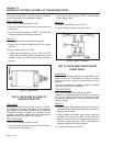
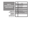
Figure 11. 12 Position Connector on Inverter
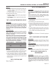
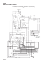
STATOR TESTS
TEST 32 - POWER SUPPLY WINDING TEST
1. Disconnect the 12 position cable from the inverter.
2. Start the unit with CB1 in the OFF position.
3. Set a VOM to measure AC. Measure voltage across Pin #6
and Pin #7. The power supply voltage should be approximately
25-30 VAC at approximately 2700 rpm.
4. Turn CB1 to the ON position.
5. Voltage across the floating power supply should be approxi-
mately 30 to 34VAC at approximately 3400rpm.
6. If results are lower, there is a possible stator problem. Proceed
to Test 34.
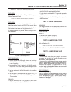
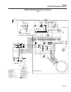
TEST 33 - TIMING WINDING TEST
1. Disconnect the timing winding from receptacle J5 on the A6060
circuit board (orange and grey wires).
2. Disconnect the 12 position harness from the inverter.
3. Two jumper wires with alligator clips are required.
4. Attach a jumper from Wire #15 (located at the fuse holder) to
Wire #14 (located at the four tab terminal block in the control
panel). This will enable fuel and ignition functions.
Page 7.2-18
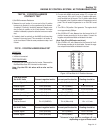
*NTC thermistor; if inverter is hot, resistance may be several kOhm lower. If inverter is cold, resistance
may be several kOhm higher
1. Test With DVOM
Set At Diode Range Connect negative lead to: Connect positive lead to: Reading should be:
Signal Circuit Pin 2 (En/Com) Pin 1 (PWM1) 1.25 to 1.5 v
Signal Circuit Pin 2 (En/Com) Pin 3 (PWM2) 1.25 to 1.5 v
2. Test With DVOM
Set At Resistance Range Connect negative lead to: Connect positive lead to: Reading should be:
Temperature Circuit Pin 9 (0 V) Pin 10 (TEMP) *10 kOhm @ 25°C
±500 Ohms
Sense Circuit Pin 9 (0 V) Pin 11 (SENSE) 20 kOhm ± 200 Ohm
3. Test With DVOM
Set At AC Volts Connect negative lead to: Connect positive lead to: Reading should be:
Fan Test Pin 9 (0 V) Pin 4 (Wire #14) See Note
NOTE: Use a ballpoint pen or small screwdriver to spin the blades of the inverter-cooling fan.
Momentarily, observe a reading of 10 - 30 mV.