


Section 7
DIAGNOSTIC TESTS
6
0
4
13
13
2
4
22S
11S
15
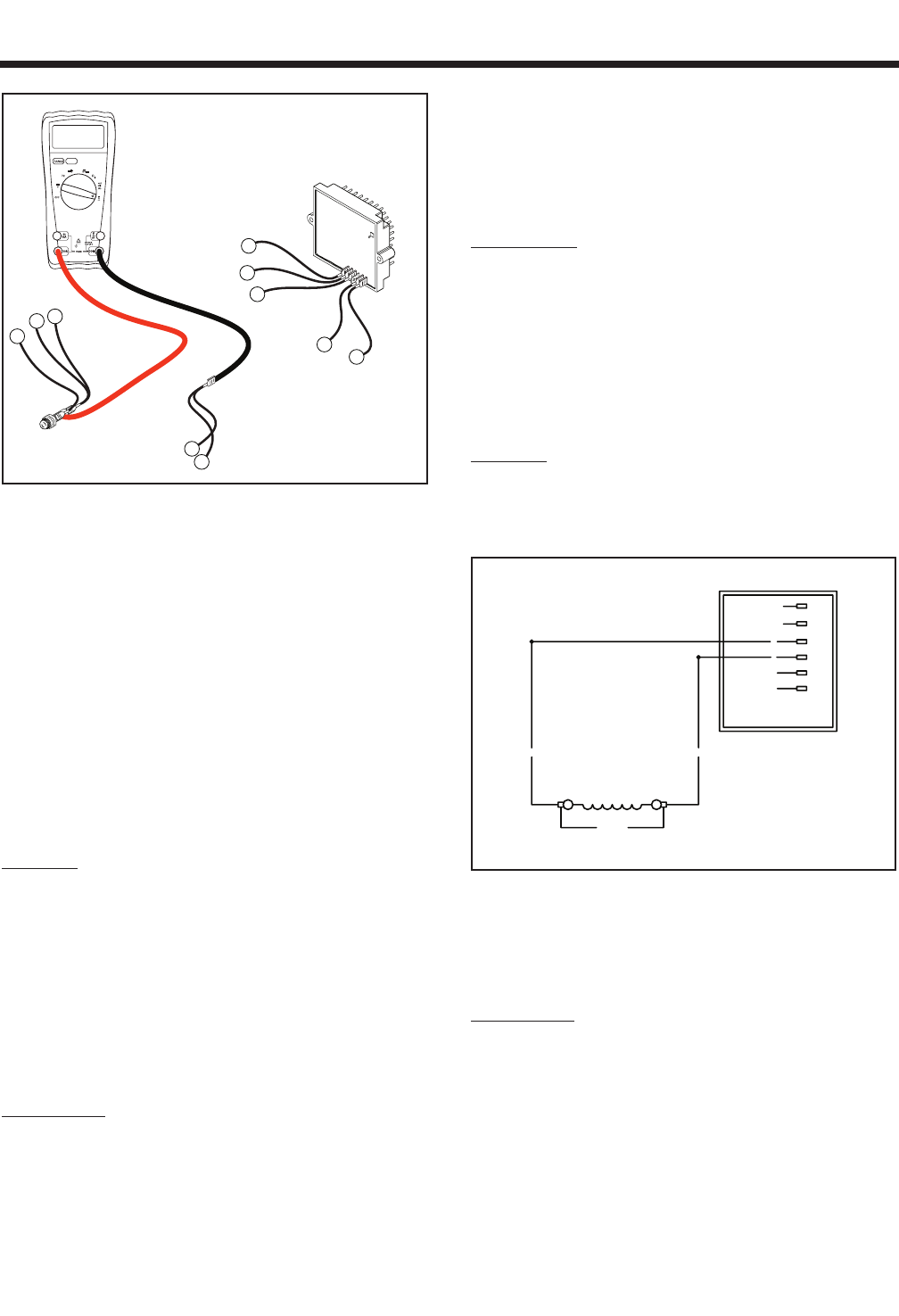
WIRES 4 REMOVED FROM
VOLTAGE REGULATOR
VOLTAGE
REGULATOR
FUSE HOLDER (F1)
RED TEST LEAD
BLACK TEST LEAD
1.11 Amp
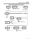
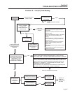
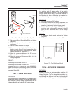
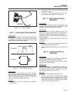
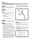
Figure 7-6. – Fixed Excitation Test, Step D
7. Re-connect Wire 11S and Wire 22S to the Voltage
Regulator.
8. Remove the jumper wire between Wire 4 and 12
volt supply.
9. Set the VOM to measure DC amps.
10. Connect one meter test lead to the 12 volt fused
battery supply Wire 15, and connect the other
meter test lead to Wire 4 (should still be discon-
nected from the VR). See Figure 7-6.
11. Start the generator. Measure the DC current.
Record the rotor amp draw.
12. Stop the generator. Re-connect Wire 4 to the
Voltage Regulator.
RESULTS:
AC Voltage across Wires 2 and 6 = _________
AC Voltage across Wires 11S and 22S = _________
Proceed to “TEST 4 RESULTS” (top of page 40).
Match all results to corresponding column in the chart.
The column letter refers to the Problem 4 flow charts
on pages 28 and 29.
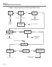
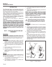
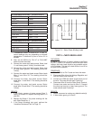
TEST 5 – CHECK FIELD BOOST
DISCUSSION:
Field boost current is delivered to the Rotor only while
the engine is being cranked. This current helps ensure
that adequate “pickup” voltage is available to turn the
Voltage Regulator on and build AC output voltage.
Loss of the field boost function may or may not result
in a problem with AC output voltage. If the Rotor’s
residual magnetism is sufficient to turn the Regulator
on, loss of the function may go unnoticed. However, if
the Rotor’s residual magnetism is not enough to turn
the Regulator on, loss of field boost can result in fail-
ure of the unit to generate an output voltage.
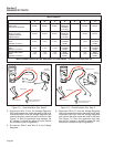
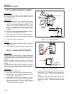
PROCEDURE:
1. Set VOM to measure DC voltage.
2. Disconnect Wire 4 from the Voltage Regulator and
connect the positive (+) test lead to it. Connect the
negative (-) test lead to a clean frame ground.
3. Set the Start-Stop Switch to “START.” During
cranking only, measure DC voltage. It should
read 3-5 VDC. Reconnect Wire 4 to the Voltage
Regulator.
RESULTS:
1. If field boost checks good, replace the Voltage
Regulator.
2. If voltage is not measured, replace the PCB.
REGULATOR
VOLTAGE
2
2
0
6
22S
4
11S
6
0
4
22S
11S
BA
40
FIELD
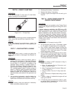
Figure 7-7. – The Field Boost Circuit
TEST 6 – TEST STATOR DPE WINDING
DISCUSSION:
An open circuit in the Stator excitation windings will
result in a loss of unregulated excitation current to the
Voltage Regulator. The flow of regulated excitation cur-
rent to the Rotor will then terminate and the unit’s AC
output voltage will drop to a value that is commensurate
with the rotor’s residual magnetism (about 5 - 12 VAC).
Page 39