


Section 2
MAJOR GENERATOR COMPONENTS
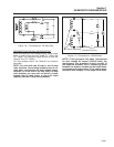
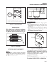
ROTOR ASSEMBLY
The Rotor is sometimes called the “revolving field”,
since it provides the magnetic field that induces a
voltage into the stationary Stator windings. Slip rings
on the Rotor shaft allow excitation current from the
voltage regulator to be delivered to the Rotor wind-
ings. The Rotor is driven by the engine at a constant
speed through a pulley and belt arrangement.
All generator models in this manual utilize a 2-pole
Rotor, i.e., one having a single north and a single
south pole. This type of Rotor must be driven at 3600
rpm for a 60 Hertz AC output, or at 3000 rpm for a 50
Hertz output.
Slip rings may be cleaned. If dull or tarnished, clean them
with fine sandpaper (a 400 grit wet sandpaper is recom-
mended). DO NOT USE ANY MATERIAL CONTAINING
METALLIC GRIT TO CLEAN SLIP RINGS.
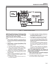
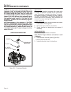
STATOR ASSEMBLY
The Stator is “sandwiched” between the upper and
lower bearing carriers and retained in that position by
four Stator studs. A total of eight (8) leads are brought
out of the Stator as follows:
1. Four (4) Stator power winding output leads (Wires
No. 11, 22, 33 and 44). These leads deliver power
to connected electrical loads.
2. Stator power winding “sensing” leads (11S and
22S). These leads deliver an “actual voltage sig-
nal to the electronic Voltage Regulator.
3. Two excitation winding output leads (No. 2 and 6).
These leads deliver unregulated excitation current
to the voltage regulator.
Page 8
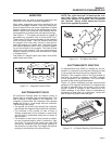
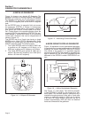
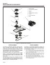
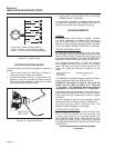
Figure 2-1. Exploded View of Generator
1
6
8
2
4
5
7
1. BRUSH HOLDER
2. UPPER BEARING CARRIER
3. STATOR
4. ROTOR
5. LOWER BEARING CARRIER
6. ENGINE
7. PULLEYS AND BELT
8. FANS
8
3