


CHANGING ENGINE OIL
Refer to maintenance performed by authorized service
facilities for engine oil and filter change frequencies.
Drain the oil while the engine is still warm from run-
ning. This means warm up the engine, shut it down
and drain immediately as follows:
1. Remove OIL DRAIN HOSE from its retaining
clip.
2. Loosen and remove OIL DRAIN HOSE CAP. Drain
oil completely into suitable container.
3. When all oil has drained, install and tighten OIL
DRAIN HOSE CAP, and re-install into its retaining
clip.
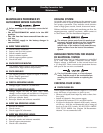
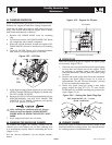
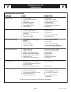
4. Turn OIL FILTER (Figure 10.2) counterclockwise
and remove. Properly dispose of old filter.
Figure 10.2 – Oil Filter
Oil
Filter
5. Apply light coating of new engine oil to seal of new
oil filter.-Install FILTER and tighten by hand only.
DO NOT OVER TIGHTEN.
6. Remove OIL FILL CAP. Add recommended oil (see
SPECIFICATIONS). DO NOT FILL ABOVE THE
DIPSTICK “FULL” MARK. Crankcase oil capacity
is 4.0 U.S. quarts (3.8 liters).
After refilling the crankcase with oil, always
check oil level on dipstick. NEVER OPERATE
ENGINE WITH OIL BELOW THE DIPSTICK “ADD”
MARK.
7. Start engine and check for oil leaks.
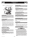
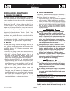
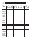
CHANGING THE ENGINE AIR CLEANER
To replace the engine air cleaner, remove the air
cleaner cover and replace the air filter making sure
it is positioned properly before reattaching the cover
(Figure 10.3).
See the “Service Schedule,” for air cleaner mainte-
nance.
Figure 10.3 – Engine Air Cleaner
Air Cleaner
(Doors Removed for Clarity)
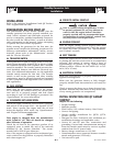
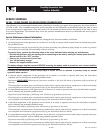
SPARK PLUGS
Reset the spark plug gap or replace the spark plugs
as necessary (Figure 10.4).
1. Clean the area around the base of the spark plugs
to keep dirt and debris out of the engine. Clean
by scraping or washing using a wire brush and
commercial solvent. Do not blast the spark plugs
to clean.
2. Remove the spark plugs and check the condition.
Replace the spark plugs if worn or if reuse is
questionable. See the “Service Schedule,” Section
6, for recommended inspection.
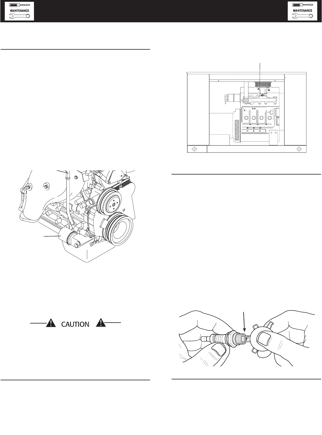
3. Check the spark plug gap using a wire feeler
gauge. Adjust the gap to 1.07-1.17 mm (0.042-
0.046 inch) by carefully bending the ground elec-
trode (Figure 10.4).
Figure 10.4 – Setting the Spark Plug Gap
COOLANT CHANGE
Every year, have an Authorized Service Facility drain,
flush and refill the cooling system. See “Specifications”
for cooling system recommendations.
Standby Generator Sets
Maintenance
10-3
Maint010 Rev. 0 02/06
SET PLUG GAP AT 1.07 - 1.17 mm
(0.042 - 0.046 inch)