


1.10.2 ENGINE SPECIFICATIONS
Make..............................................................................Mitsubishi
Displacement ..............................................92 inches
3
(1.5 liters)
Cylinder Arrangement......................................................4, in-line
Valve Arrangement................................................Overhead Cam
Firing Order........................................................................1-3-4-2
Number of Main Bearings............................................................5
Compression Ratio ..............................................................9 to 1
No. of Teeth on Flywheel ........................................................104
Ignition Timing
at 1800 rpm ..................................................35 degrees BTDC
Spark Plug Gap ..................................................0.020-0.025 inch
Recommended Spark Plugs
Champion ....................................................................RN11YC4
Oil Pressure....................................................................30-50 psi
Crankcase Oil Capacity........................3.0 U.S. quarts (2.8 liters)
Recommended Engine Oil........................................SAE 15W-40
Type of Cooling System ..................Pressurized, closed recovery
Cooling Fan ..............................................................Pusher Type
Cooling System Capacity ......................2 U.S. gallons (7.6 liters)
Recommended Coolant............................Use a 50-50 mixture of
ethylene glycol base.
1.11 FUEL CONSUMPTION
15 kW Models
Using Natural Gas ........................................277 cu. ft. per hour
Using LP Gas..............................110 cubic ft.(3.1 gal.) per hour
NOTE:
Fuel consumption is given at rated maximum con-
tinuous power output when using natural gas
rated at 1000 Btu per cubic foot and LP gas rated
2520 Btu per cubic foot. Actual fuel consumption
obtained may vary depending on such variables as
applied load, ambient temperature, engine condi-
tions and other environmental factors.
Fuel pressure for a natural gas set up should be five
inches to 14 inches of water column (0.18 to 0.5
psi) at all load ranges.
Fuel pressure for an LP vapor set up should be 11
inches to 14 inches of water column (0.4 to 0.5
psi) at all load ranges.
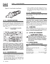
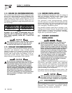
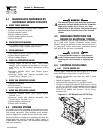
1.12 RECONFIGURING THE FUEL
SYSTEM
NOTE:
All models are configured for natural gas from the
factory.
To reconfigure the fuel system from NG to LP, follow
these steps:
1. Turn the main gas supply off.
2. Remove the carburetor fuel hose from the outlet
port (Port 1) of the demand regulator (Figure
1.8).
3. Remove the brass hose fitting from the outlet port
(Port 1) of the demand regulator.
4. Remove pipe plug from Port 2.
5. Install brass hose fitting into Port 2.
6. Install pipe plug into Port 1.
7. Connect carburetor gas hose to brass fitting.
8. Tighten all clamps and plugs.
9. Make sure fuel supply is of the proper pressure
and type for configuration.
10. Reverse the procedure to convert back to natural
gas.
Figure 1.8 — Reconfigure the Fuel System
NOTE:
Port 1 is for NG only and Port 2 is for LP vapor
only. No provision for simultaneous fuels has been
made.
Serious injury or damage may occur if not con-
figured properly. Please consult a dealer with
any questions.
1.13 TORQUE SPECIFICATIONS
Cylinder Head ............................................15 (+ 90° + 90°) ft.lb.
Intake Manifold ................................................................13 ft.lb.
Exhaust Manifold..............................................................13 ft.lb.
!
DANGER
NG FUEL SYSTEM
LP FUEL SYSTEM
Port 1
Port 2
FUEL HOSE
BRASS HOSE
FITTING
HOUSING
PORTS
OUT
PORT 2
PLUG
FUEL HOSE
BRASS HOSE
FITTING
HOUSING
PORTS
PLUG
OUT
PORT 1
Section 1 — General Information
Carrier Liquid-cooled 15 kW Generators
Carrier 7