


12 Carrier
Before starting the generator for the first time, the
installer must complete the following procedures. For
follow-up maintenance information and/or service
intervals, please refer to Section 4, “Maintenance.”
2.11.2 TRANSFER SWITCH
If this generator is used to supply power to any elec-
trical system normally powered by an electric utility,
the National Electrical Code requires that a transfer
switch be installed. The transfer switch prevents elec-
trical backfeed between two different electrical sys-
tems. (For additional information, see the applicable
transfer switch manual for this unit.) The transfer
switch, as well as the generator and other standby
components, must be properly located and mounted
in strict compliance with applicable codes, standards
and regulations.
2.11.3 FUEL SYSTEM
Make sure the fuel supply system to the generator (a)
delivers the correct fuel at the correct pressure and
(b) is properly purged and leak tested according to
code. No fuel leakage is permitted. See
“Specifications” (Section 1.10) for more information.
2.11.4 GENERATOR SET LUBRICATION
Check the engine crankcase oil level before operating
and add oil to the proper level – the dipstick “FULL”
mark. Never operate the engine with the oil level
below the dipstick “ADD” mark. See “Specifications”
(Section 1.10) and “Engine Oil Recommendations”
(Section 1.14).
NOTE:
This engine is shipped from the manufacturer
with 15W-40 oil. This oil should be changed after
30 hours of operation.
2.11.5 ENGINE COOLANT
Have the engine cooling system properly filled with
the recommended coolant mixture. Check the system
for leaks and other problems. See “Specifications”
(Section 1.10) and “Coolant” (Section 1.15).
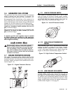
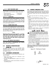
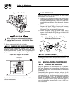
2.11.6 BELT TENSION
Check the engine fan belt tension and condition prior
to placing the unit into service and at recommended
intervals. Belt tension is correct when a force of
approximately 22 pounds (10 kg), applied midway
between pulleys, deflects the belt about 3/8- to 5/8-
inch (10 to 16 mm).
2.11.7 ELECTRICAL SYSTEM
Make sure the generator is properly connected to an
approved earth ground and/or ground rod.
Make sure the generator battery is fully charged,
properly installed and interconnected, and ready for
use.
Check to ensure that there are no loose electrical con-
nections. Restrain any loose wires to keep them clear
of any moving generator set components.
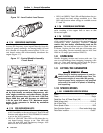
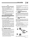
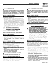
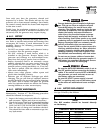
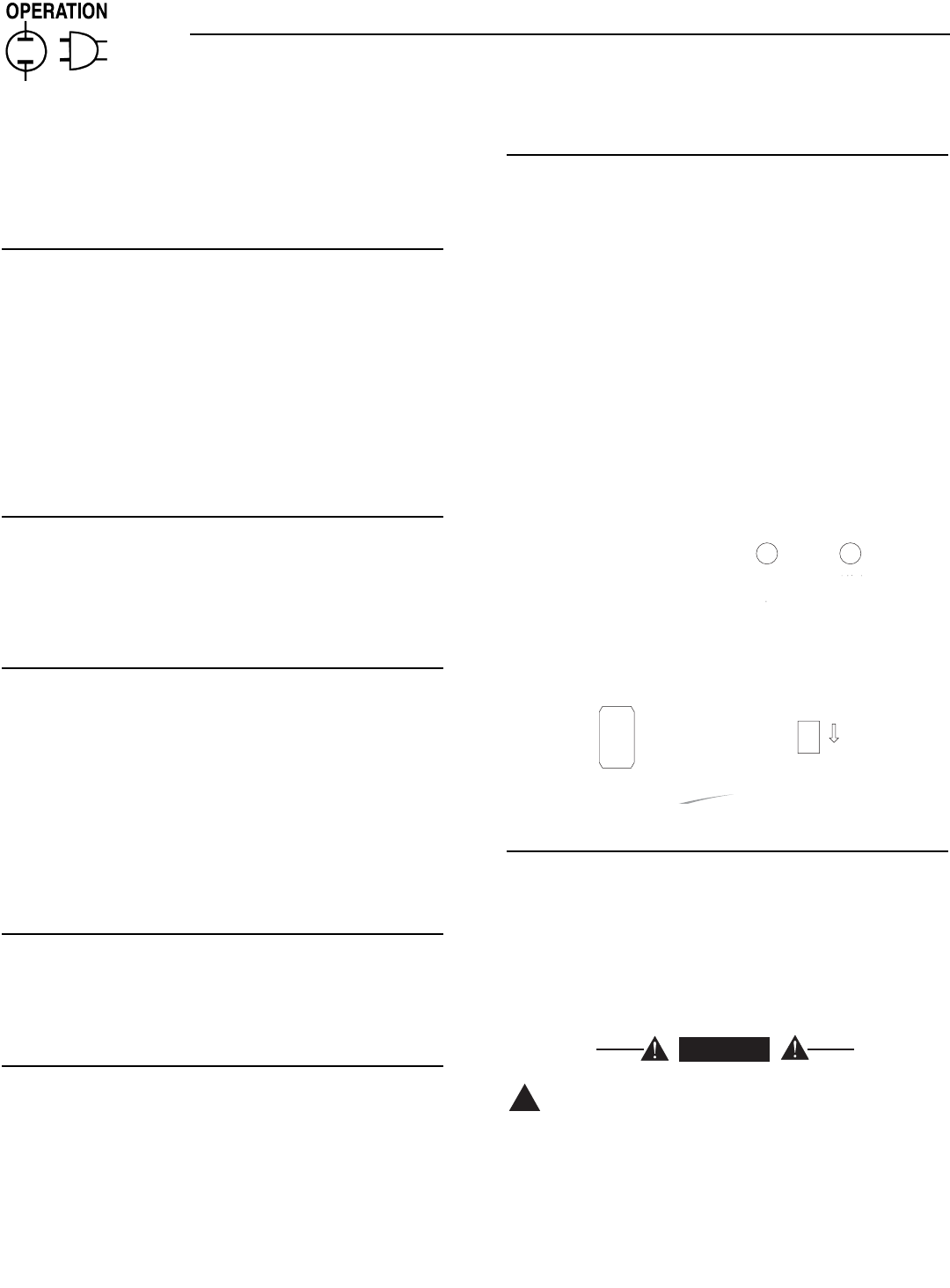
3.1 CONTROL CONSOLE
COMPONENTS
The components of a liquid-cooled generator control
console (Figure 3.1) are as follows:
Figure 3.1 - Liquid-Cooled Generator Panel
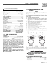
3.1.1 AUTO/OFF/MANUAL SWITCH
Use this three-position switch as follows:
• Set the switch to AUTO for fully automatic opera-
tion. See “Automatic Operation”, Section 3.4.
• Set switch to MANUAL position to crank and start
the generator engine.
• Set switch to OFF position to shut down an oper-
ating engine. With OFF selected, operation will not
be possible.
With switch set to AUTO, engine can crank and
start suddenly without warning. Such automat-
ic start up normally occurs when UTILITY source
voltage drops below a pre-set level. To prevent
possible injury that might be caused by such
sudden starts, set AUTO/OFF/MANUAL switch
to OFF before working on or around the unit.
Then, place a "DO NOT OPERATE" tag on con-
trol console.
!
DANGER
AUTO
MANUAL
OFF
FUSE
15-A
AGC
FAULT
INDICATOR
SET
EXERCISE
TIME
ON
HOUR METER
Section 3 — Operation
Carrier Liquid-cooled 15 kW Generators