


1.9 LOCATION
1.9.1 GENERATOR
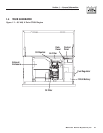
Install the generator set, in its protective enclosure,
outdoors, where adequate cooling and ventilating air
is always available. Consider these factors:
• Install the unit where air inlet and outlet openings
will not become obstructed by leaves, grass, snow,
etc. If prevailing winds will cause blowing or drift-
ing, you may need to consider using a windbreak
to protect the unit.
• Install the generator on high ground where water
levels will not rise and endanger it.
• Allow sufficient room on all sides of the generator
for maintenance and servicing. A good rule is to
allow 3 feet of space on all sides.
• Where strong prevailing winds blow from one
direction, face the generator air inlet openings to
the prevailing winds.
• Install the generator as close as possible to the fuel
supply, to reduce the length of piping.
• Install the generator as close as possible to the
transfer switch. HOWEVER, REMEMBER THAT
LAWS OR CODES MAY REGULATE THE DIS-
TANCE.
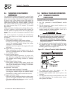
1.9.2 TRANSFER SWITCH
The transfer switch shipped with this generator is
rated 100 amps maximum at 120/240 volts AC single
phase. The enclosure of the transfer switch is NEMA
1. This type of enclosure is intended for indoor use
only. Follow these rules:
• Install the transfer switch indoors on a firm, stur-
dy supporting structure.
• To prevent switch distortion, level the switch if
necessary. This can be done by placing washers
between the switch enclosure and mounting sur-
face.
• Never install the switch where water or any corro-
sive substance might drip onto the enclosure.
• Protect the switch at all times against excessive
moisture, dust, dirt, lint, construction grit and cor-
rosive vapors.
1.10 BATTERY INSTALLATION
Fill the battery with the proper electrolyte fluid if nec-
essary and have the battery fully charged before
installing it.
Before installing and connecting the battery, complete
the following steps:
1. Set the generator's Auto/Off/Manual switch to
OFF.
2. Turn off utility power supply to the transfer
switch.
If the Auto/Off/Manual switch is not set to its
OFF position, the generator can crank and start
as soon as the battery cables are connected. If
the utility power supply is not turned off,
sparking can occur at the battery posts and
cause an explosion.
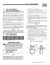
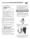
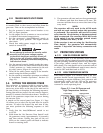
Battery cables were factory connected at the genera-
tor (Figure 1.5). Connect cables to battery posts as
follows:
3. Connect the red battery cable (from starter con-
tactor) to the battery post indicated by a positive,
POS or (+).
4. Connect the black battery cable (from frame
ground) to the battery post indicated by a nega-
tive, NEG or (—).
NOTE:
Damage will result if battery connections are made
in reverse.
Figure 1.5 – Battery Cable Connections
NOTE:
Your generator is equipped with a battery trickle
charger that is active when your unit is set up for
automatic operation. With the battery installed
and utility power source voltage available to the
transfer switch, the battery receives a trickle
charge while the engine is not running, to prevent
self-discharge. The trickle charger is designed to
help extend the life of your battery by maintaining
the battery when the unit is not running. The
trickle charge feature cannot be used to recharge
a discharged battery.
1.11 THE BATTERY
Servicing of the battery is to be performed or super-
vised by personnel knowledgeable of batteries and
the required precautions. Keep unauthorized person-
nel away from batteries.
When replacing the battery, use the following type of
battery: Group 26/26R 12VDC, 550 cold-cranking
DANGER
◆
◆
Section 1 — General Information
Air-cooled 8.5 kW Generator
8 Generac
®
Power Systems, Inc.