


Generac Portable Products SVP5000 Generator
6
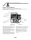
OPERATING THE GENERATOR
CAUTION! Never start or stop, the engine with
electrical loads connected to the unit and with
the connected devices turned ON.
Starting the Engine
DANGER! Breathing Hazard! Never run
engine indoors or in enclosed poorly ventilated
areas. Engine exhaust contains carbon
monoxide, an odorless and deadly gas.
WARNING! Burn Hazard! Temperature of
muffler and nearby areas may exceed 150°F
(65°C). Avoid these areas.
Unplug all electrical loads from generator
receptacles before starting the engine.
Make sure the unit is in a level position.
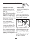
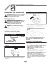
Open the fuel shutoff valve (Figure 3).
Move the choke lever to the Choke position
(Figure 4).
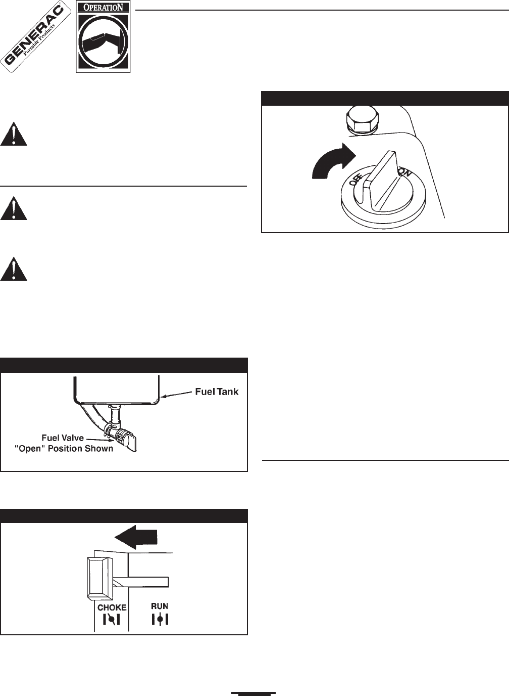
Set the engine control switch to the On position
(Figure 5).
Grasp starter grip and pull slowly until you feel some
resistance. Then pull cord out with rapid full arm
stroke. Let rope return slowly. Do Not let rope snap
back against starter.
When engine starts, move choke lever to Run
position.
NOTE: If engine fails to start after 3 pulls, move the
choke lever to Run and pull starter rope again.
NOTE: If the engine still fails to start, check for proper
oil level in crankcase. Unit is equipped with a low oil
shutdown system. See engine owners manual for
information regarding the low oil shutdown system.
NOTE: If engine fires, but does not continue to run,
move choke lever to Run and repeat starting
instructions.
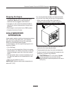
Connecting Electrical Loads
Let engine stabilize and warm up for a few minutes
after starting.
Plug in and turn on the desired 120 and/or 240 Volt
AC, single phase, 60 Hz electrical loads.
Do Not connect 240 Volt loads to the 120 Volt
duplex receptacles.
Do Not connect 3phase loads to the generator.
Do Not connect 50 Hz loads to the generator.
DO NOT OVERLOAD THE GENERATOR. Add up
the rated watts (or amps) of all loads to be
connected at one time. This total should not be
greater than the rated wattage/amperage capacity of
the generator. See Dont Overload the Generator
on page 9.
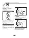
Figure 3 Fuel ShutOff Valve
Figure 4 Choke Lever
Figure 5 Engine Control Switch