


15
3.3 GENERAL RECOMMENDATIONS
The warranty of the generator does not cover items that have
been subjected to operator abuse or negligence. To receive full
value from the warranty, the operator must maintain the
generator as instructed in this manual.
Some adjustments will need to be made periodically to properly
maintain the generator.
All adjustments in the Maintenance section (3) of this manual
should be made at least once each season. Follow the
requirements in the "Maintenance Schedule" chart on page 14.
NOTE: Once a year you should replace the spark plug
and replace the air filter. A new spark plug and clean
air filter assure proper fuel-air mixture and help your
engine run better and last longer.
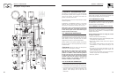
3.3.1 GENERATOR MAINTENANCE
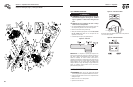
Generator maintenance consists of keeping the unit clean and dry.
Operate and store the unit in a clean dry environment where it will
not be exposed to excessive dust, dirt, moisture or any corrosive
vapors. Cooling air slots in the generator must not become
clogged with snow, leaves, or any other foreign material.
Check the cleanliness of the generator frequently and clean when
dust, dirt, oil, moisture or other foreign substances are visible on
its exterior surface.
ƽCAUTION! Never insert any object or tool through the air
cooling slots, even if the engine is not running.
Note: DO NOT use a garden hose to clean generator.
Water can enter the engine fuel system and cause
problems. In addition, if water enters the generator
through cooling air slots, some water will be retained
in voids and crevices of the rotor and stator winding
insulation. Water and dirt buildup on the generator
internal windings will eventually decrease the
insulation resistance of these windings.
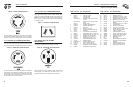
3.3.2 TO CLEAN THE GENERATOR
• Use a damp cloth to wipe exterior surfaces clean.
• A soft, bristle brush may be used to loosen caked on dirt, oil, etc.
• A vacuum cleaner may be used to pick up loose dirt and debris.
• Low pressure air (not to exceed 25 psi) may be used to blow
away dirt. Inspect cooling air slots and openings on the
generator. These openings must be kept clean and
unobstructed.
3.3.3 ENGINE MAINTENANCE
DANGER! When working on the generator, always disconnect
negative cable from battery. Also disconnect spark plug wires
from spark plug and keep wire away from spark plug.
3.3.4 CHECKING OIL LEVEL
See the “BEFORE STARTING THE GENERATOR” section on page
10 for information on checking the oil level. The oil level should
be checked before each use, or at least every eight hours of
operation. Keep the oil level maintained.
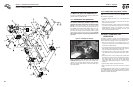
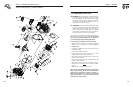
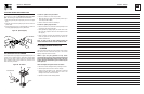
3.3.5 CHANGING THE OIL AND OIL FILTER
Change the oil and filter after the first eight hours of operation.
Change the oil every 100 hours thereafter. If you are running this
unit under dirty or dusty conditions, or in extremely hot weather,
change the oil more often.
Use the following instructions to change the oil while
the engine is still warm:
• Clean area around oil drain hose and plug.
• Remove oil drain plug from end of hose and oil fill plug to drain
oil completely into a suitable container.
• When oil has completely drained, install oil drain plug and
tighten securely.
• Place a suitable container beneath the oil filter and turn filter
counterclockwise to remove. Discard according to local
regulations.
• Coat gasket of new filter with clean engine oil. Turn filter
clockwise until gasket contacts lightly with filter adapter. Then
tighten an additional 3/4 turn.
• Fill oil sump with recommended oil. (See “Before Starting the
Generator” on page 10 for oil recommendations).
• Wipe up any spilled oil.
Section 3 — Maintenance
Commercial-Industrial-Residential Portable Generator System
GOVERNOR
ACTUATOR
30
85
87a
86
87
GREEN
WHITE
Y
X
OFF
ON
J2
J1
+
-
2
22
77A
66A
11
BA
44S
11S
6
44
REGULATOR
VOLTAGE
WHITE
Y
X
G
30A TWI
STLOK
120/240 V
120V/20 A
HOT
HOT
3
1
WHITE
WHITE
5
LINE
4
LOAD
2
C.B.
30A
C.B.
30A
C.B.
20A
C.B.
20A
C.B.
30A
30A
C.B.
TRANSFORMERS
IDLE CONTROL
CONTROL
ON/OFF
IDLE
0
LOP
FSS
SP2
IM2
D
IM1
SP1
D
IC
SSR
66
77
10A AUTO
RESET BKR
12Vdc O
UTLET
ENGIN
E WIRING
77
66
6
2
77A
66A
77
66A
13A
15
15
15
15
15
0
0
0
0
0
0
0
0
0
18
15
13
13
167
167
15B
11
11
11
44
44
22
22
22
22
11
11
11
11
11
11
44
44
44
44
44
44
44
0
0
15A
BLK
229
229
11A
11A
44A
44A
44B
11B
11C
11D
44D
22
22
22
0
0
0
0
0
0
0
0
0
0
0
GFCI
DUPLEX
120V/20 A
HOT
3
1
HOT
WHITE
4
5
WHITE
2
G
WHITE
G
WHITE
120V/30 A
TWISTLOK
120V/30 A
TWISTLOK
F1
0
0
0
0
0
15
15
0
0
0
0
4
13
15
R1
D2
1414
14
14
14
14
14
14
14
17
15B
BLK
0
0
ELECTRONIC
GOVERNOR /
ENGINE SHUTDOWN P.C. B.
CB1
50A
C.B.
55
55
55A
55
55A
11
0
11
44
86
86
86
167
83
83
BLACK
BATTERY
12V
RED
SM
SC
86
13
16
16
15
15
14
14
0
0
SWITCH
SCR
TB1
TB2
RECTIFI
ER
BATTERY
CHARGE
BATTERY
CHARGE
RECTIFI
ER
18
1
2
4
5
6
7
8
9
10
11
3
12
PIN #
4
4
4
RED
1
2
3
4
6
7
8
9
10
5
11
12
PIN #
167
0
0
44C
0
22
22
22
22
22
22
GND
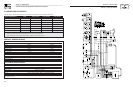
LEGEND
BA - BR
USH ASS
EMBLY
CB1 - 5AMP AUT O RESE T BREAKER
D - ENGINE SHU TDOWN DIODE
D2 - 600 V 12A DIODE
F1 - 10A FUSE
FSS - F UEL SHU
T OFF SOLENOID
GND - G ROUND BAR
IM1 - IGNITION
MODULE, CYL. 1
IM2 - I
GNITION MODULE
, CYL. 2
LOP - L
OW OIL PRESSU RE
R1 - 25 OHM, 2 5W RESISTOR
SC - STARTER CONT
ACT OR
SM - ST
ARTER MOTOR
SP1 - S
PARK PL
UG, CYL. 1
SP2 - S PARK PLUG, CYL. 2
SSR - S TART / STOP RELAY
TB1, TB
2 - TERMINAL BLOCK
SCR - S
TARTER CONTAC TOR RELAY
120/240 V
50A OUT
LET
(START)
0
15
17
RUN
STOP
22
22
22
22
0
22
22
66
77A
0
0
0
0
0
0
14
14
13
9
10
12
5
12
6
4
8
CLOSES T TO BEARING
0
4
STATOR
PIN 6
PIN 5
PIN 4
PIN 3
PIN 2
PIN 1
44S
162
11S
0
4
6
162
55
55A
11S
44S
55A
55
77
66
10
98
7
6
5
4
321
11
12
22
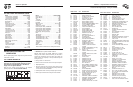
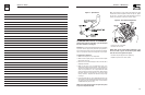
Section 6 — Electrical Data
Commercial-Industrial-Residential Portable Generator System
Wiring Diagram – Drawing No. 0E0228