


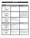

OVERVOLTAGE ALARM
If the generator voltage rises above 110% for >3 seconds, an
alarm will be issued.
If the generator voltage rises above 130% for >0.2 seconds, an
alarm will be issued.
INTERNAL FAILURE SHUTDOWN ALARM
Any internal failure that can be detected such as corrupted
firmware will cause this shutdown alarm. This alarm cannot be
cleared.
CANBUS ALARM
Where applicable, if the Canbus communications link fails to com-
municate, a “Canbus Alarm” will be generated. This only applies
to systems with external ignition modules. The alarm may be
generated if:
1. The physical link is broken.
2. The Ignition Module fails or resets.
3. The Nexus Controller fails or resets.
4. Having the Battery Chargers 120 VAC connected without a
battery installed.
5. A blown 10 amp Ignition Module fuse (approximately 12
inches away from the starter).
6. A blown 25 amp system fuse (located approximately 12
inches away from the DC alternator).
NOTE:
The “Canbus Alarm” will not clear on its own. To clear the
alarm, press the “enter” key to acknowledge the alarm. The
alarm will clear and if the fault is still present, the alarm will
reoccur.
IGNITION ALARM
When an ignition alarm occurs, a generic message “Ignition Fault”
will be displayed as the fault code.
MAINTENANCE WARNING
When a maintenance period expires, a warning message will be
posted. The warning can be reset by hitting the Enter key. Resetting
will clear the warning and reset the maintenance counters for the
condition annunciated. The history log will reflect the maintenance
warning.
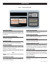
ALARM CANCEL
When the generator is shut down due to a latching alarm, the Auto
/Off/ Manual switch must be set to the off position and the ENTER
key pressed to unlatch any active fault and clear the corresponding
fault alarm message.
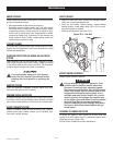
COMMON ALARM RELAY
The common alarm relay will be activated if there is a shutdown
alarm. It will not activate on warnings or indicate that the Auto/Off/
Manual switch is in the OFF position. The OFF position will clear
the alarms and the relay. The relay will not be used to indicate a
generator is not activated.
The common alarm connections are wired to a set of potential-
free (dry) contacts on the Nexus controller board. These Normally
Open (N.O.) contacts close when an alarm condition occurs and
are used to activate a remote signaling device. The circuit is rated
for a maximum of 130mA at 24 VDC. The connections are a short
set of free hanging wires that exit the engine harness loom directly
behind the Nexus Control Panel and are labeled numbers 209 and
210.
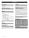
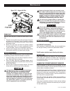
MAINTENANCE ALERTS
Maintenance alerts will be provided for these conditions.
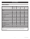
SERVICE SCHEDULE ‘A’
Inspect Accessory Drive Alert 1yr / 100hrs*
Coolant Change & Flush 1yr / 100hrs
Inspect Spark Plugs Alert 1yr / 100hrs
Change Oil & Filter Alert 1yr / 100hrs*
Inspect Battery Alert 1yr / 100hrs
Change / Inspect Air Filter Alert 1yr / 100hrs
Clean/Inspect Air Inlet & Exhaust 6mo / 50hrs*
* Items require a 3 month / 30 hour break-in change or check.
SERVICE SCHEDULE ‘B’
Change / Inspect spark plugs alert 2yr/ 250hr
8-6
CntrlNexus001 Rev. E 12/11
Control Panel