


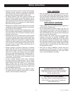
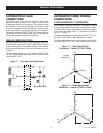
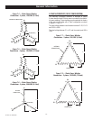
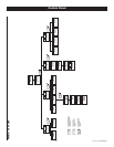

Figure 7.4 — Stator Power Winding
Connections - 3-phase, 120/208V (6 Lead)
E3
E2
00 (NEUTRAL)
INTERNAL CONNECTIONS
E1
L-L
L-N
S1
S1
S4
S4
S6
S6
S3
S3
S5
S5
S2
S2
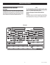
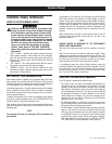
Figure 7.5 — Stator Power Winding
Connections - 3-phase, 120/208V (12 Lead)
E3
E2
E1
L-L
L-N
S7
S1
S10
S4
S12
S6
S9
S3
S5
S11
S2
S8
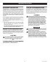
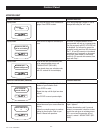
Figure 7.6 — Stator Power Winding
Connections - 3-phase, 346/600V (6 Lead)
E1
S1
S6
S5
S4
S2
E2
S3
E3
L - N
L - L
INTERNAL
CONNECTIONS
00 (NEUTRAL)
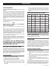
3-PHASE ALTERNATORS ("DELTA" CONFIGURATION)
The Stationary Emergency Generator is designed to supply
3-phase electrical loads. Electric power is produced in the alterna-
tor power windings. These windings were connected at the factory
to the main circuit breaker with a “Delta” configuration as shown
in Figures 7.7 and 7.8.
The rated voltage between circuit breaker terminals E1-E2, E1-E3
and E2-E3 is 240V.
The rated voltage between E1 or E3 and the neutral point 00 is
120V.
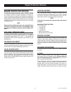
Figure 7.7 — Stator Power Winding
Connections - 3-phase, 120/240V (6 Lead)
E2
E1 E3
INTERNAL
CONNECTIONS
S1
S6
S5
S4
S2
S3
L - N
L - L
00 (NEUTRAL)
Figure 7.8 — Stator Power Winding
Connections - 3-phase, 120/240V (12 Lead)
E2
E1 E3
S1
S12
S11
S8 S6
S5 S9
S10
S2
S3
L - N
L - L
00 (NEUTRAL)
7-2
ACConn007 Rev. B 05/10
General Information