


Generac
®
Power Systems, Inc. 15
Upon restoration of utility source voltage above a pre-
set level, generator circuit board action signals the
transfer switch to transfer loads back to that power
supply. After retransfer, the engine is signalled to shut
down.
The actual sequence of operation is controlled by
sensors and timers on a control logic circuit board,
as follows:
A.Utility Voltage Dropout Sensor
• This sensor monitors utility source voltage.
• If utility source voltage drops below about 70 per-
cent of the nominal supply voltage, the sensor
energizes a 15-second timer.
• Once the timer has expired, the engine will crank
and start.
B.Engine Warm-up Time Delay
• This mechanism lets the engine warm up for
about 10 seconds before the load is transferred
to a standby source.
C.Standby Voltage Sensor
• This sensor monitors generator AC output volt-
age. When the voltage has reached 50 percent of
the nominal rated voltage, transfer to standby
can occur.
D.Utility Voltage Pickup Sensor
• This sensor monitors utility power supply volt-
age. When that voltage is restored to above 70
percent of the nominal source voltage, a retrans-
fer time delay starts timing.
E.Retransfer Time Delay
• This timer runs for about 15 seconds.
• At end of a 15-second delay, circuit board action
de-energizes the transfer relay in the transfer
switch.
• Retransfer to utility power source then occurs.
F. Engine Cool-down Timer
• When the load is transferred back to utility power
source, the engine cool-down timer starts timing.
• The timer will run for about one minute, and the
generator will then shut down.
3.5 MANUAL TRANSFER OPERATION
3.5.1 TRANSFER TO GENERATOR
POWER SOURCE
To start the generator and activate the transfer switch
manually, proceed as follows:
1. Set the generator’s main circuit breaker to its
OFF (or open) position.
2. Set the generator’s AUTO/OFF/MANUAL switch
to OFF.
3. Turn OFF the utility power supply to the transfer
switch using the means provided (such as a
utility main line circuit breaker).
Do not attempt to activate the transfer switch
manually until all power voltage supplies to
the switch have been positively turned off.
Failure to turn off all power voltage supplies
may result in extremely hazardous and possibly
fatal electrical shock.
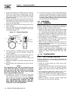
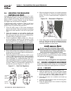
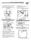
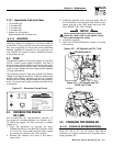
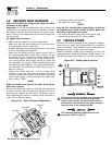
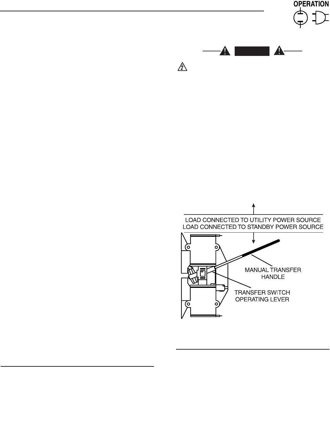
4. Use the manual transfer handle inside the trans-
fer switch to move the main contacts to their
“Standby” position, i.e., loads connected to the
standby power source (Figure 3.2).
5. To crank and start the engine, set the
AUTO/OFF/MANUAL switch to MANUAL.
6. Let the engine stabilize and warm up for a few
minutes.
7. Set the generator’s main circuit breaker to its ON
(or closed) position. The standby power source
now powers the loads.
Figure 3.2 – Manual Transfer Switch Operation
3.5.2 TRANSFER BACK TO UTILITY POWER
SOURCE
When utility power has been restored, transfer back
to that source and shut down the generator. This can
be accomplished as follows:
1. Set the generator’s main circuit breaker to its
OFF (or open) position.
2. Let the engine run for a minute or two at no-load
to stabilize the internal temperatures.
3. Set the generator’s AUTO/OFF/MANUAL switch to
its OFF (or open) position. The engine should
shut down.
4. Check that utility power supply to the transfer
switch is turned OFF.
DANGER
Section 3 — Operation
Generac Air-cooled 7 kW, 12 kW and 15 kW Generators