


14 Generac
®
Power Systems, Inc.
Section 3 — Operation
Generac Air-cooled 7 kW, 12 kW and 15 kW Generators
NOTE:
The voltage regulator is housed above the genera-
tor's control panel. The regulator maintains a volt-
age in direct proportion to frequency. For example,
at 62 Hertz, line-to-neutral voltage will be 124 volts.
3.1 BREAK-IN PROCEDURE
Once the unit has been installed, with utility power
connected to the transfer switch, and all electrical
checks have been made, it is strongly recommended
that the following “Break-in Procedure” be completed
to ensure correct generator operation in the future.
1. Set the generator’s AUTO/OFF/MANUAL switch to
AUTO.
2. Turn OFF the utility power supply to the transfer
switch using the means provided (such as a utili-
ty main line circuit breaker).
3. The unit will start, and the transfer switch will
transfer to standby.
4. Run the unit for one hour at 25 percent load.
5. Run the unit for one hour at 50 percent load.
6. Run the unit for one hour at 75 percent load.
7. Run the unit for one hour at 100 percent load.
8. Turn ON the utility power supply to the transfer
switch, which will allow the transfer switch to
transfer back to utility power. The unit will con-
tinue to run for one minute and then shut down.
9. Allow the unit to cool.
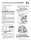
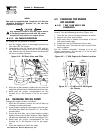
10. Drain the oil and remove the oil filter. Replace the
oil filter according to Section 4.4, “Changing the
Oil Filter”. Replace the oil with synthetic oil as
recommended in Section 4.3, “Changing the
Engine Oil”.
11. The generator is now ready for service.
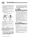
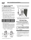
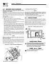
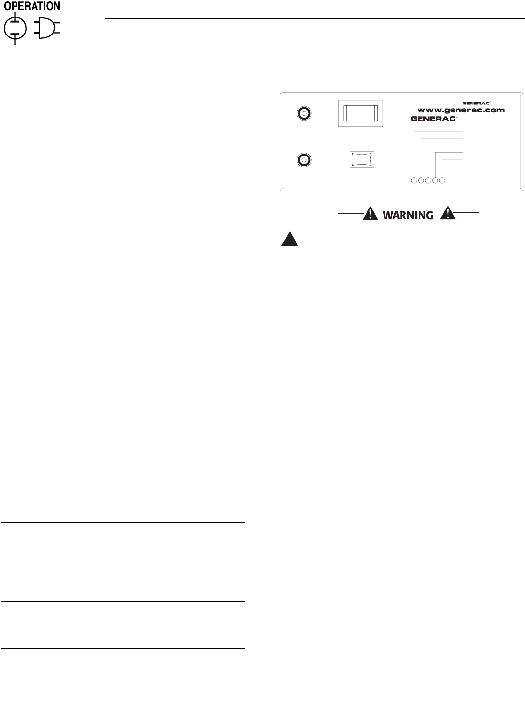
3.2 USING THE AUTO/OFF/MANUAL
SWITCH (FIGURE 3.1)
3.2.1 “AUTO” POSITION
Selecting this switch position activates fully automatic
system operation. It also permits starting and exercising
of the engine every seven days with the exercise timer (see
Section 3.6). This position also is used for remote start-
ing, when it is set up.
3.2.2 “OFF” POSITION
This switch position shuts down the engine. This
position also prevents automatic operation.
3.2.3 “MANUAL” POSITION
Set the switch to MANUAL to crank and start the
engine. Transfer to standby power will not occur
unless there is a utility failure.
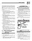
Figure 3.1 – Generator Control Panel
With the switch set to AUTO, the engine may
crank and start at any time without warning.
Such automatic starting normally occurs when
utility power source voltage drops below a pre-
set level or during the normal exercise cycle. To
prevent possible injury that might be caused by
such sudden starts, always set the switch to
OFF and remove both fuses before working on
or around the generator or transfer switch.
Then, place a “Do Not Operate” tag on the gen-
erator panel and on the transfer switch.
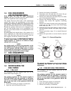
3.3 AUTOMATIC TRANSFER
OPERATION
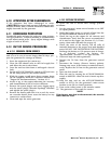
To select automatic operation, do the following:
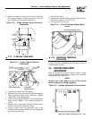
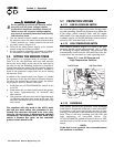
1. Make sure the transfer switch main contacts are
set to their “Utility” position, i.e., loads connected
to the utility power source (Figure 3.2).
2. Be sure that normal utility power source voltage
is available to transfer switch terminal lugs N1
and N2.
3. Set the generator’s AUTO/OFF/MANUAL switch to
AUTO.
4. Set the generator’s main circuit breaker to its ON
(or closed) position.
With the preceding steps complete, the generator will
start automatically when utility source voltage drops
below a preset level. After the unit starts, loads are
transferred to the standby power source. Refer to
Section 3.4, “Sequence of Automatic Operation.”
3.4 SEQUENCE OF AUTOMATIC
OPERATION
The generator’s control panel houses a control logic
circuit board. This board constantly monitors utility
power source voltage. Should that voltage drop below
a preset level, circuit board action will signal the
engine to crank and start. After the engine starts, the
circuit board signals the transfer switch to activate
and connect load circuits to the standby power sup-
ply (load terminal lugs T1/T2 connect to terminal
lugs E1/E2).
!
HIGH TEMP.
OVER SPEED
LOW OIL
SYSTEM SET
OVER CRANK
MAN.
SET
OFFAUTO
15A
FUSE
EXERCISE
TIME
R
POWER SYSTEMS, INC.
Locate your nearest dealer at:
R
FUSE
5A
EXERCISER NOT SET
NO U T IL ITY SE N S E
4FLASHINGREDLEDS=
FLASHING GREEN LED=