


32
Route conduit so it does not interfere with generator move-•
ment.
If using metallic conduit, vapor seal the end of the conduit •
where it enters the junction box. Do this because flexible metal-
lic conduit is not vaporproof along its entire length.
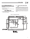
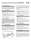
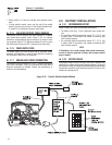
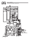
2.7.5 ISOLATING DIFFERENT POWER SOURCES
Connections from the junction box must terminate in a double-
pole, double-throw transfer switch (Figure 2.18). An alternate
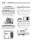
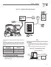
method for isolating different power sources is by using an isolat-
ing receptacle (Figure 2.19). Whichever method is use, be certain
that both power sources are NOT connected at the same time.
2.7.6 POWER SUPPLY CORD
The power supply cord must comply with all applicable codes,
standards and regulations. It must be large enough to handle the
full amperage to which it will be subjected.
2.7.7 GROUND FAULT CIRCUIT INTERRUPTERS
The National Electrical Code (NFPA 70, 551-7) requires that ground
fault circuit interrupters (GFCIs) on all external and some internal
electrical receptacles be installed. Contact the manufacturer or
dealer for recommendations.
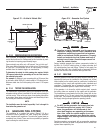
2.8 BATTERY INSTALLATION
2.8.1 RECOMMENDED BATTERY
Install a battery that meets the following requirements:
The battery must be a 12-volt, automotive type storage bat-•
tery.
For prevailing ambient temperatures above 32° F (0° C), use •
a battery rated 70 amp-hours and capable of delivering 400
cold-cranking amperes.
For prevailing ambient temperatures below 32° F (0° C), use •
a battery rated 95 amp-hours and capable of delivering 400
cold-cranking amperes.
NOTE:
If the battery is to be used to power other vehicle accessories,
as well as start the generator, a battery with a larger capacity
may be needed.
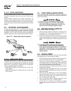
2.8.2 BATTERY CABLES
Using battery cables that are too long or too small in diameter may
cause a drop in voltage, which causes starting problems. For the best
cold weather starting, the voltage drop between battery terminals and
the generator connection point should not exceed 0.12 volts per 100
amperes of cranking current.
Section 2 – Installation
Recreational Vehicle Generator
Figure 2.18 – Transfer Switch Isolation Method