


26
DANGER
Never use discharged cooling air for heating or
permit such air to enter the vehicle interior. This
air contains deadly carbon monoxide gas and
other poisonous, flammable or explosive gases.
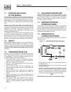
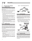
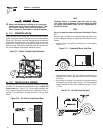
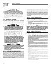
2.3.1 GENERATOR AIRFLOW
Engine operation drives cooling fans for the two-stage cooling air
system. A pressure fan draws cooling air into the top of the generator
(Figure 2.9). This airflow cools the engine/generator and electronic
components. The second part of the cooling system, a suction fan,
draws air that is heated from a hot engine into a collector pan at the
base of the unit. This heated air (although cooler than exhaust muf-
fler) is then deflected out the bottom toward the ground.
Figure 2.9 – Airflow Through Engine/Generator
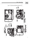
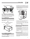
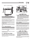
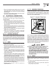
2.3.2 COOLING AIR INLET OPENINGS
The minimum size of the air inlet opening, whether the generator
is housed in a conventional compartment or not, is at least 100
square inches (see Figure 2.10). This rule applies whether inlet
air is brought in through an opening in the compartment door, an
opening in the vehicle skirt, through ductwork, or by any other
means.
Figure 2.10 – Air Inlet in Compartment Door
NOTE:
Screening, louvers or expanded metal that cover air open-
ings restrict airflow. Compensate for this by making the actual
air opening proportionately larger. See the "Compensating for
Restrictions" section.
NOTE:
Be sure to meet the minimum clearances illustrated in Figure
2.4.
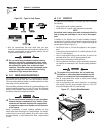
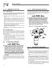
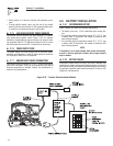
When the unit is installed on a suspended mounting system, one
of several different methods of supplying airflow may be used as
follows:
Provide a door in the vehicle skirt having an air inlet opening •
(Figure 2.11).
Figure 2.11 – Suspended Mount: Inlet Door
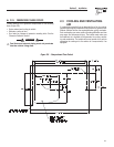
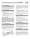
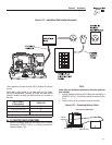
Using ductwork (Figure 2.12). The installer must be sure air is •
available to the top of the generator since air inlets are located
at the top.
By providing an opening in the vehicle skirt and space behind •
the generator for cooling airflow (Figure 2.13). Recommended
clearance behind the back of the generator is at least 1/2 inch
(13 mm).
Figure 2.12 – Air Inlet Using Ductwork
Section 2 – Installation
Recreational Vehicle Generator