


1.11 SPECIFICATIONS
1.11.1 ENGINE
Make ......................................................................................Ford
Displacement ............................................153 inches
3
(2.5 liters)
Cylinder Arrangement......................................................4, in-line
Valve Arrangement................................................Overhead Cam
Firing Order........................................................................1-3-4-2
Number of Main Bearings............................................................5
Compression Ratio..........................................................9.37 to 1
No. of Teeth on Crank ............................................................36-1
Ignition Timing (Waste Spark System)
at 1800 rpm (NG) ..........................................36 degrees BTDC
at 1800 rpm (LP vapor) ................................28` degrees BTDC
Spark Plug Gap ............................................................0.044 inch
Recommended Spark Plugs
Motorcraft ................................................................AWSF-52-C
Oil Pressure....................................................................30-50 psi
Crankcase Oil Capacity......................4.5 U.S. quarts (4.26 liters)
Recommended Engine Oil........................................SAE 15W-40
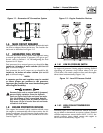
Type of Cooling System ..................Pressurized, closed recovery
Cooling Fan ..............................................................Pusher Type
Cooling System Capacity ......................2 U.S. gallons (7.6 liters)
Recommended Coolant ............Use a 50-50 mixture of ethylene
glycol base and deionized water.
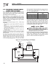
Home standby control board assembly part
number 0E9704 must be used on 1800 rpm gen-
erators.
1.12 FUEL CONSUMPTION
15 kW Models
Using Natural Gas ........................................236 cu. ft. per hour
Using LP Gas ..................................................92 cu. ft. per hour
20 kW Models
Using Natural Gas ........................................307 cu. ft. per hour
Using LP Gas ................................................122 cu. ft. per hour
25 kW Models
Using Natural Gas ........................................441 cu. ft. per hour
Using LP Gas ................................................175 cu. ft. per hour
NOTE:
Fuel consumption is given at rated maximum con-
tinuous power output when using natural gas
rated at 1000 Btu per cubic foot; or LP gas rated
2520 Btu per cubic foot. Actual fuel consumption
obtained may vary depending on such variables as
applied load, ambient temperature, engine condi-
tions and other environmental factors.
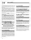
Fuel pressure for a natural gas set up should be five
inches to 14 inches of water column (0.18 to 0.5
psi) at all load ranges.
Fuel pressure for an LP vapor set up should be 11
inches to 14 inches of water column (0.4 to 0.5
psi) at all load ranges.
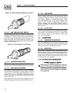
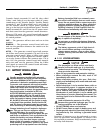
1.13 RECONFIGURING THE FUEL
SYSTEM FOR LP VAPOR
NOTE:
All models are configured for natural gas (NG)
from the factory.
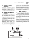
To reconfigure the fuel system from NG to LP vapor,
follow these steps:
1. Turn the main gas supply off.
!
Section 1 — General Information
Liquid-cooled 15, 20 and 25 kW Generators
7
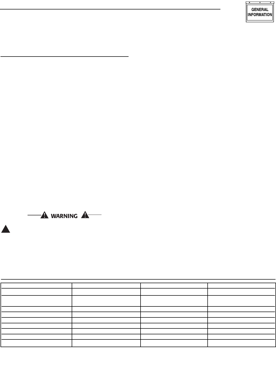
1.11.2 GENERATOR
* Rated power of generator is subject to and limited by such factors as ambient temperature, altitude, engine condition, and other fac-
tors. Engine power will decrease about 3.5% for each 1000 feet above sea level and will decrease an additional 1% for each 10°F
above 60°F. Maximum output power of the generator is limited by maximum engine power.
Single-phase Single-phase Single-phase
Model 005031-0 005028-0 005030-0
Rated Max. Cont. 25 20 15
AC Power Output (kW)*
Rated Voltage (volts) 120/240 120/240 120/240
No. of Rotor Poles 4 4 4
Driven Speed of Rotor (rpm) 1800 1800 1800
Rotor Excitation System Direct excited brush type Direct excited brush type Direct excited brush type
Type of Stator 4 Wire 4 Wire 4 Wire
Rotor Insulation Class F Class F Class F
Stator Insulation Class H Class H Class H