


Generac
®
Power Systems, Inc. 31
2.6.7 GROUND FAULT CIRCUIT
INTERRUPTERS
The National Electrical Code (NFPA 70, 551-7)
requires that you install ground fault circuit inter-
rupters (GFCIs) on all external and some internal
electrical receptacles. Contact your manufacturer or
dealer for recommendations.
2.7 BATTERY INSTALLATION
2.7.1 RECOMMENDED BATTERY
Install a battery that meets the following
requirements:
• The battery must be a 12-volt, automotive type
storage battery.
• For prevailing ambient temperatures above 32° F
(0° C), use a battery rated 70 amp-hours and capa-
ble of delivering 400 cold-cranking amperes.
• For prevailing ambient temperatures below 32° F
(0° C), use a battery rated 95 amp-hours and capa-
ble of delivering 400 cold-cranking amperes.
NOTE:
If the battery is to be used to power other vehicle
accessories, as well as start the generator, you may
need a battery with a larger capacity.
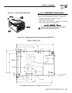
2.7.2 BATTERY CABLES
Using battery cables that are too long or too small in
diameter may cause a drop in voltage, which causes
starting problems. For the best cold weather starting,
the voltage drop between battery terminals and the
generator connection point should not exceed 0.12
volts per 100 amperes of cranking current.
PRIMEPACT generators are rated at about 100 DC
amperes of cranking current.
Select battery cables based on (a) cable length and (b)
prevailing ambient temperatures. Generally, the
longer the cable and the colder the weather, the larg-
er the cable size must be, as shown in the chart.
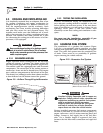
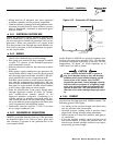
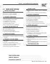
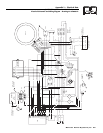
2.7.3 BATTERY CABLE CONNECTIONS
1. Connect the battery cable from the battery post or
terminal indicated by a POSITIVE, POS or (+) to
the lug on the starter contactor (Figure 2.16).
NOTE:
Check to be sure the battery cable boot for the
starter cable has been installed.
2. Connect the battery cable from the battery post
indicated by a NEGATIVE, NEG or (-) to the
frame ground connection (Figure 2.16).
3. Connect cables so the connectors are clean
and tight.
Figure 2.16 – Connecting Battery Cables
2.7.4 BATTERY COMPARTMENT
Install the generator battery in its own, vented com-
partment. Place the battery compartment away from
any source of heat, sparks or flame.
Provide ventilation openings in the battery compart-
ment. The minimum size of openings should be 2
square inches at the top of the compartment. Mount
the battery on a strong, rigid supporting structure,
where leaks and spills of battery fluid will not cause
damage.
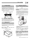
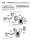
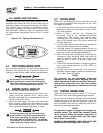
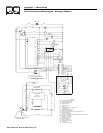
2.8 OPTIONAL ACCESSORIES
A plug-in receptacle (Figure 2.17) is provided on the
generator set. Use this receptacle to connect an
optional remote-mounted start/stop panel to the gen-
erator. Installation of such a panel will permit you to
start and stop the generator engine from any conve-
nient location inside the vehicle.
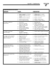
Figure 2.17 – Remote Panel Plug-in Receptacle
12.00"
12.00"
14
0
17
15
18
14A
1
3
2
5
4
6
0
14
17
18
14A
15
15
17
14A
18
14
0
No.
WIRE
WIRE
COLOR
RED
YELLOW
ORANGE
WHITE
BLUE
BROWN
12.0 (305)
LENGTH (mm)
12.0 (305)
12.0 (305)
12.0 (305)
12.0 (305)
12.0 (305)
FUNCTION
GROUND
ENGINE RUN SIGNAL
12 VDC
START
STOP
PRIME
P/N: 0D9099-B
◆
NEG
FUEL
POS
◆
◆
◆
◆
Section 2 – Installation
QUIETPACT 40G Recreational Vehicle Generator