


GEH-5304A
33
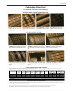
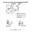
Commutator Check Chart
For Comparing Commutator Surface Markings
SATISFACTORY COMMUTATOR SURFACES
LIGHT TAN FILM over entire commu-
tator surface is one of many normal
conditions often seen on a well-
functioning machine-
MOTTLED SURFACE with random film
pattern is probably the most frequently
observed condition of commutators in
industry.
SLOT BAR-MARKING, a slightly dark-
er film appears on bars in a definite
pattern related to number of conductors
per slot.
HEAVY FILM can appear over entire
area of efficient and normal commu-
tator and, if uniform, is quite accept-
able.
STREAKING on the commutator surface signals the
beginning of serious metal transfer to the carbon
brush. Check the chart below for possible causes.
THREADING of commutator with fine lines results
when excessive metal transfer occurs. It usually
leads to resurfacing of commutator and rapid brush
wear.
GROOVING is a mechanical condition caused by
abrasive material in the brush or atmosphere. If
grooves form, start corrective action.
COPPER DRAG, an abnormal build-up of commutator
material, forms most often at trailing edge of bar.
Con-dition is rare, but can cause flashover if not
checked.
PITCH BAR-MARKING produces low or burned spots
on the commutator surface. The number of these
markings equals half or all the number of poles on the
motor.
HEAVY SLOT BAR-MARKING can involve etching
of trailing edge of commutator bar. Pattern is re-
lated to number of conductors per slot.
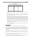
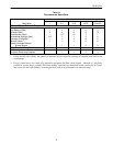
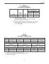
CAUSES OF POOR COMMUTATOR CONDITION
Frequent visual inspection of commutator surfaces can warn you when any of the above conditions are developing so that you can take early corrective action. The chart below may indi-
cate some possible causes of these conditions, suggesting the proper productive maintenance.
Type of Brush
Light Unbalanced Brush In Use Contamination
Electrical Electrical Electrical Armature Shunt Pressure Abrasive Porous Abrasive
Adjustment Overload Load Connection Field (Light) Vibration Brush Brush Gas Dust
Streaking X X X X X X
Threading X X X X
Grooving XX
Copper Drag XXX X
Pitch Bar-Marking X X X X X
Slot Bar-Making X X X
HOW TO GET THE MOST VALUE FROM THIS CHART
The purpose of the Commutator Check Chart is to help you spot undesirable commutator conditions as they develop so you can take corrective action before the condition becomes serious.
This chart will also serve as an aid in recognizing satisfactory surfaces.
The box chart above indicates the importance of selecting the correct brush and having the right operating conditions for optimum brush life and commutator wear.
For additional information or help with carbon brush application or commutation problems. Contact your nearest GE Sales Office or Distributor.
WATCH FOR THESE DANGER