


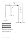
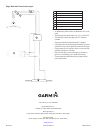
1.2 L and 2.0 L Hydraulic Pump Installation Instructions 3
notice
The following is a general procedure for bleeding a hydraulic steering
system. Refer to the instructions provided by the manufacturer of
the steering system for more-specic information about bleeding the
system.
Before you bleed the hydraulic system, ensure that all hose connections
are complete and fully tightened.
1. Complete an action:
• If the helm reservoir contains insufcient uid, ll it with the
appropriate amount of hydraulic uid.
• If the helm reservoir contains excess uid, remove the excess to
avoid uid overow during the bleeding process.
2. Manually steer the helm to both cylinder stops.
3. Manually steer the helm fully to port.
4. Open a bypass valve at the cylinder port.
5. Turn the helm slowly to port for three minutes.
6. Close the cylinder bypass valve.
7. Add uid to the helm reservoir if necessary.
8. Repeat steps 2 through 7 until the helm reservoir remains full.
notice
To ensure long life of all parts, apply corrosion blocker to the pump at
least twice yearly.
After the pump installation is complete and all hydraulic connections
and electrical connections are made, apply a marine-rated corrosion
blocker to the pump.
If your boat has an unbalanced cylinder steering system, you must
install the optional unbalanced valve kit.
1. Remove the four screws that hold the manifold to the pump body
and remove the manifold from the pump body.
2. Replace the o-rings on the pump body with the o-rings supplied in
the unbalanced kit.
3. Place the unbalanced valve between the pump body and the
manifold, with the o-rings on the unbalanced valve facing the
manifold.
4. Use the longer screws supplied in the unbalanced kit to connect
the manifold and unbalanced valve to the pump body. Use thread-
locking compound, and tighten the screws to 35 lbf-in. (3.95 N-m).
notice
Do not unscrew the brass screws more than the specied amount.
Do not operate the system with the brass screws fully tightened.
Before you calibrate the unbalanced valve, you must install the
unbalanced valve and connect the hydraulic lines. The brass calibration
screws on the sides of the unbalanced valve adjust the valve.
1. Tighten both calibration screws until they stop.
2. Measure the distance by which each screw protrudes.
3. If the screws do not protrude the same distance, loosen the shorter
screw until they protrude the same distance.
4. Unscrew each screw by two and one-half turns.
notice
When disengaging the shutoff valve, do not force the three brass screws
past the stopping point. Forcing the screws past the stopping point may
permanently damage the manifold.
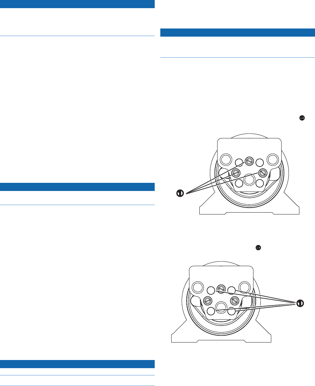
The 1.2/2.0 L pump features a shutoff valve that isolates the pump from
the hydraulic system for troubleshooting and repairing the system.
When the shutoff valve is engaged, the boat steers normally, and the
autopilot cannot control the steering system. When the shutoff valve is
engaged, you can remove the pump from the system for repair without
disconnecting any hydraulic lines.
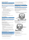
Complete an action:
• To engage the shutoff valve, fully tighten the three screws
➊
.
• To disengage the shutoff valve, fully loosen the three screws.
➊
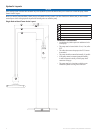
Before you remove the pump from the hydraulic system, you must
engage the shutoff valve (page 3).
1. Remove the four socket-head cap screws
➊
that connect the
manifold to the pump.
➊
2. Disconnect the pump from the ECU.
3. Remove the pump from its mounting location.
1. Mount the pump in its original location.
2. Connect the pump to the ECU.
3. Connect the manifold to the pump using the four socket-head cap
screws.
4. Disengage the shutoff valve (page 3).