


3
Assembly Instructions
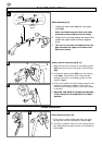
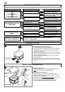
Cable Restraint (D) & (E)
1.Form loop in mains cable and push the loop
through the slot as illustrated in picture (D).
2.To secure, position loop over the hook and pull
the cable back through the slot as illustrated in
picture (E).
C
B
2
1
4
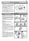
Safety Guard Assembly (B) & (C)
1.Align the arrow on the top of the safety guard
(B1) with the arrow on the side of the trimmer
(B2).
2.Locate the safety guard (B3) over the cutting
head (B4). Ensure the nylon lines are fed
through the hole in the safety guard as illus-
trated in fig B.
3.Push into location and turn safety guard in the
direction illustrated in Fig C, until a click is
heard and the safety guard is securely locked
in position.
• ENSURE THE SAFETY GUARD IS SECURE-
LY IN PLACE BY ATTEMPTING TO TWIST
GUARD.
D E
Cable Restraint
3
A
1
2
3
1
2
Cable
Protection
Sleeve
Shaft Assembly (A)
1. Locate the lower shaft (A1) into the upper
shaft (A2).
Note: the black internal cable and cable
protection sleeve (A3) are self-locating
2. Grasp firmly and hold steady the lower shaft.
Locate the upper shaft and snap together
firmly.
• The unit is correctly assembled when the
gap between the upper and lower shaft
has been closed.