


12 Multimeter
TESTING DIODES
11
TESTING DIODES
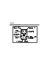
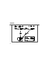
1. Insert the test leads in the jacks.
2. Put the slide-switch in the continuity/ohms position. The meter selects either the
continuity/diode (R G) or ohms (e) function.
If ohms is selected, press [g] to toggle to the continuity/diode function. To toggle
the beeper on or off in continuity/diode test, press [V]. R is displayed when the
beeper is enabled.
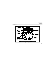
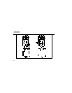
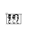
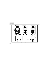
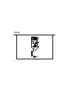
3. Touch probes to the diode (Figure 5A). A forward-voltage drop of about 0.6 V
(typical for a silicon diode) causes the meter to beep once.
4. Reverse probes (Figure 5B). If the diode is good, OL is displayed. If the diode is
shorted (Figure 5C), the beeper sounds continuously in at least one direction.
If the diode is open, OL is displayed in both directions.