


12 Multimeter
TESTING CONTINUITY AND MEASURING RESISTANCE
9
TESTING CONTINUITY AND MEASURING RESISTANCE
1. Insert the test leads in the jacks, and turn off power to the circuit under test.
External voltage across the components causes invalid readings.
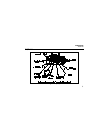
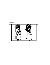
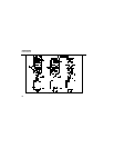
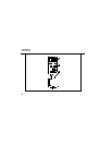
2. Put the slide-switch in the continuity/ohms position (Figure 4).
To toggle between the continuity/diode and ohms functions, press [g].
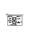
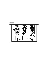
3. Touch the probes to the test points.
4. In ohms, read the resistance on the display.
In continuity test, the beeper sounds continuously if continuity exists (resistance
< 25 Ω.). Opens and shorts longer than 250 µs are detected. On the Fluke 12,
short-to-open and open-to-short transitions can be captured and visually
displayed. See “Capturing Continuity Intermittents”.
If the meter detects a voltage greater in magnitude than about 4.5 V and the meter is
not in the manual range mode, the meter automatically changes to the voltage
measurement function. (See “CHEK AND HOW TO USE IT”.)