8
6. IRON DISC TOGGLE:
When this toggle switch is ipped ON, the 1270 will operate in IRON DISC
mode. When operating in this mode, the IRON DISC control becomes
active and the NORMAL DISC control will be ignored. The NORMAL DISC
control can be momentarily re-engaged without changing the IRON
DISC setting by pushing the MODE TRIGGER switch forward.
7. SILENCER:
Used in conjunction with the NORMAL DISC control, this feature reduces
the normal clicks and pops heard while going over trash. With the toggle
“off”, you will hear clicks and pops and partial signals for maximum audio
target information. With the toggle “on”, the 1270 operates in a newly
developed 3rd derivative SILENCER mode, eliminating the clicks, pops,
and partial target responses for a quieter mode of operation. This mode
is especially designed for those who wish to eliminate excessive partial
audio responses in high trash areas.
8. LOW BATTERY LED:
This LED will start to blink to alert you when the batteries are nearing their
end of life. When the LED starts to blink you have approximately 1 hour*
of usage left before performance degradation begins to occur (*ac-
tual time will vary depending on usage). The rst stage of performance
degradation is loss of the audio threshold when the SENSITIVITY control
is at maximum.
9. HEADPHONE JACK:
This jack accepts most stereo headphones with ¼ inch diameter plugs.
When headphones are used, the speaker is disabled. Headphones are
benecial when hunting in noisy areas. Faint and deeper signals will be
heard better!
10. MODE TRIGGER SWITCH:
The 1270 MODE TRIGGER switch allows you to conveniently switch be-
tween modes of operation without losing your panel control settings.
The switch has three positions: normal (center position), pinpoint (pulled
position), and swap (pushed position).
• PINPOINT - Pulling the MODE TRIGGER toward yourself will cause the
1270 to operate in No-Motion, All-Metal Pinpoint mode. This mode
allows you to “pinpoint” the exact location over a buried target for
faster and easier retrieval.
• NORMAL - In the MODE TRIGGER’s center position, the 1270 operates
in “primary” operating mode set by the front panel controls.
• SWAP - Pushing (and holding) the MODE TRIGGER forward causes the
1270 to switch to the “secondary” operating mode set by the front
panel controls
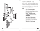
PRIMARY AND SECONDARY OPERATING MODES >
CONTROLS & FUNCTIONS
SEARCH TECHNIQUES
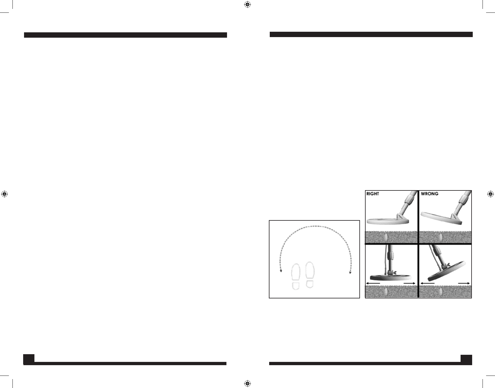
NO- MOTION PINPOINT
1. When the target “beep” is heard, make an “X” over the target, as
described above, to determine the target area.
2. Move the coil away from the target area, and lower the coil to the
ground.
3. Pull, and hold the MODE TRIGGER switch.
4. Raise the coil about 1/2 inch; move back across the target area.
5. Stop the coil at the center of the loudest response.
6. Repeat this one more time, moving your coil from side to side. Your
target should be directly below the center of the coil.
7. For larger targets, place the coil on the ground, closer to the center
of the target. The closer you are to the target center when you pull
the MODE TRIGGER switch, the more of the target will be “tuned-out”.
The target signal response will appear smaller and even easier to pin-
point.
8. IMPORTANT: Be careful not to pull the Pinpoint MODE TRIGGER switch
while directly over the target. This may “tune-out” the entire target,
and you will get no target response.
13
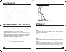
Figure #3
Figure #4
1270manual-.indd 8 6/13/06 2:50:11 PM


