STEP 5.
Adjust the length and the coil angles so that the search coil rests at
on the ground about 12 inches in front of your foot. Your arm should be
straight and relaxed. Proper length will greatly reduce arm fatigue.
STEP 6.
When the stem length is properly adjusted, tighten the lower lock nut,
and the coil wing nut. CAUTION: Never use a pliers or anything other than
your hand to tighten either lock nut or wing nut.
STEP 7.
Disconnect the search-coil cable from the control housing and wrap it
around the stem. A loose cable near the search coil may cause false
signals, but don’t wrap it so tightly that it pulls against the housing or
search coils. Reconnect the search coil cable to the control housing.
Again, nger tighten only.
STEP 8.
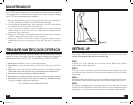
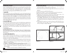
With the coil angle and the shaft length properly adjusted, you should
be able to move into your “search” position. (see gure 1)
STEP 9.
Standing with the 1270, the search coil should be parallel to the ground
and no more than 2 inches off the ground, while your arm is straight.
Remember, the closer your coil is to the target, the better chance you
have of detecting it in normal soil conditions (although, there may be
occasions that lifting the coil off the ground an inch or two will be help-
ful, such as hunting in heavily mineralized soil).
SETTING UP
6
A “False Signal” occurs when something sounds like a good
target, but is not. Your 1270 does a great job of discriminating,
but bad “targets” with similar electrical characteristics can fool
it. Large pieces of trash or items very close to the search coil will
occasionally sound “good”. Experience is the best teacher. As
you accumulate more hours with your 1270, you will soon learn
how to distinguish “false signals”. Initially when you pass over a
target, and get a good response, you will nd that crossing over the
target once or twice more, the signal will break up or completely
disappear.
Here are some sources of false signals and the solution.
1. Electrical Interference: Caused by radio and TV towers, power lines,
or other metal detectors.
SOLUTION: Move farther away from the source, slow down the sweep
speed, or lower the sensitivity.
2. Highly Mineralized Soil: Soils with a high iron or salt content.
SOLUTION: Reduce the sensitivity, raise the discrimination level, or
if searching in the ALL-METAL GROUND ADJUST mode, readjust the
ground adjust setting.
3. Extremely Trashy Areas: May result in a lot of “chatter”.
SOLUTION: Utilize the SILENCER mode, adjust the discrimination level
(the use of the IRON DISC mode can be very helpful here), or reduce
the sensitivity. In some areas, a smaller coil will be benecial to better
achieve target seperation.
4. Metal Interference: The 1270 will pick up metal ABOVE and on the
SIDE of the coil, as well as under. WATCH FOR: Large metal structures,
your digging tool, metal in shoes and your coil cable hanging loose
above the coil.
Your 1270 comes equipped with two 9-volt standard transistor radio bat-
teries. Should your low battery indicator LED start to blink, replacement in
approximately one hour will be necessary (less than one hour with NiCd
batteries). Locate the two battery compartments on the underside of
the CONTROL HOUSING. Gently push the clip on the front end IN and
UP. Pull the nylon tab to remove the batteries. Make note of the polarity
(+ / -) of your new batteries. The (+) or Positive side is the smaller of the
two contacts on the battery. Match that with the (+) inside the 1270
battery compartment. Slide the top of the battery in pushing against
the copper contacts. Gently push the bottom of the battery into the
compartment. Replace the Battery Cover.
15
BATTERY REPLACEMENT
FALSE SIGNALS
1270manual-.indd 6 6/13/06 2:50:10 PM


