


25
00
Troubleshooting, Adjustment & Service
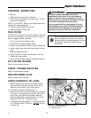
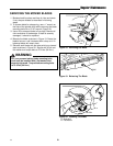
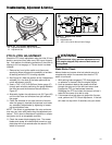
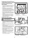
Figure 24. Parking Brake Adjustment
A. Brake Spring
B. Adjustment Nut
PARKING BRAKE ADJUSTMENT
1. Disengage the PTO, stop the engine, block the front
wheels, remove the ignition key, and engage the
parking brake.
2. Jack up the rear of the machine and secure with
jackstands. Remove both drive tires.
3. Locate the brake spring (A, Figure 24).
4. With the parking brake engaged, measure the com-
pressed spring length. The spring should be 1-
15/16” - 2” (4.9 - 5.0cm) when compressed.
5. If the spring is not within this range, release the park-
ing brake and turn the adjustment nut (B, Figure 24)
to compress or release the spring.
6. Engage the parking brake and remeasure the spring.
A
B
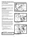
SHOCK SPRING ADJUSTMENT
The shock assembly can be adjusted to vary the amount
of pre-load applied to the springs. This allows the oper-
ator to customize the ride according to operator’s weight
and/or operating conditions.
Less Pre-Load:
• Light operator weight
• Softer, more cushioned ride
• Best for relatively flat terrain
More Pre-Load:
• Heavy operator weight
• Stiffer, more rigid ride
• Better handling and greater stability on hilly terrain
To adjust the spring pre-load:
1. Park machine on a flat, level surface. Disengage the
PTO, stop the engine and engage the parking brake.
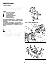
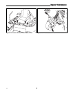
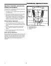
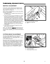
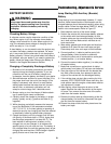
2. See Figure 25. Using the supplied spanner wrench
(p/n 22853), insert the tip of the wrench into the
notch in the pre-load adjuster. While holding the
wrench in place with one hand, turn CLOCKWISE to
increase the pre-load, turn COUNTER-CLOCKWISE
to decrease the pre-load. Make sure both shocks
are set to the same amount of pre-load.
INCREASE
DECREASE
Spanner
Wrench
Location
Figure 25. Shock Spring Adjustment
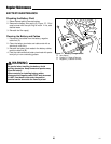
WARNING
Use two hands when adjusting the shock springs.
This will prevent the wrench from slipping while
pressure is being applied.