


Not for
Reproduction
46
www.ferrisindustries.com
Troubleshooting, Adjustment & Repair
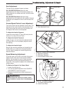
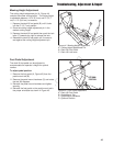
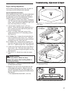
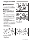
Figure 47. Deck Lift Pedal & Pin Position
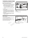
Measure 1st
Measure 2nd
Measure 1st
Measure 2nd
Inner Rod
Outer Rod
Inner Rod
Outer Rod
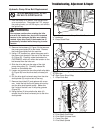
Adjust Here
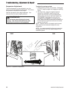
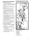
Figure 46. Measure the Inner & Outer Lift Rods
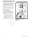
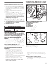
Figure 48. Adjust the Inner & Outer Lift Rods
Adjust Here
3” (7,6 cm)
Deck Lift Rod Timing Adjustment
1. Park machine on a flat, level surface. Disengage
the PTO, stop the engine and engage the parking
brake. Rear tires must be inflated to 18 psi (1,24
bar); front tires to 25 psi (1,72 bar).
2. To check the inner lift rod timing, measure and
record the distance between the inner lift pivots
and the inner rod pivots. Repeat for other side of
unit. See Figure 46.
3. To check the outer lift rod timing, measure and
record the distance between the outer lift pivots
and the outer rod pivots. Repeat for other side of
unit. See Figure 46.
4. If the measurements for the inner rods are equal,
and the measurements for the outer rods are
equal, no further adjustment is required. If the
measurements are NOT equal (greater than 1/8”
(3,17 mm) difference), adjustment is required,
continue with Step 5.
5. Refer to Figure 47. Lock the deck lift pedal in the
5” (12,7 cm) position. Remove the cutting height
adjustment pin and lower the mower deck.
6. To ensure that the deck is in the lowest position,
push the pedal by hand towards the rear of the
unit and install the height adjustment pin in the 3”
(7.6 cm) position to hold in place.
7. Block up the mower deck until all hanger chains
are slack.
8. Refer to Figure 48. To adjust the inner lift rod,
loosen the jam nut on the front ball joint then
remove the 1/2” hardware fastening the ball joint
the lift pivot arm. Turn the ball joint clockwise to
shorten the distance between the rod pivots or
counterclockwise to lengthen the distance between
the rod pivots. Reinstall the ball joint on the lift
pivot arm and secure with the 1/2” hardware
previously removed. Tighten the jam nut against
the lift rod.
9. Refer to Figure 48. To adjust the outer lift rod,
loosen the jam nut on the front ball joint then
remove the 1/2” hardware fastening the ball joint
the lift pivot arm. Turn the ball joint clockwise to
shorten the distance between the rod pivots or
counterclockwise to lengthen the distance between
the rod pivots. Reinstall the ball joint on the lift
pivot arm and secure with the 1/2” hardware
previously removed. Tighten the jam nut against
the lift rod.
10. Remove blocks from under the mower deck.
11. Remove the cutting height adjustment pin from in
front of the deck lift pedal arm. Lift mower deck
and reinstall adjustment pin in desired mowing
height.