


40
www.ferrisindustries.com
Troubleshooting
Troubleshooting, Adjustment & Service
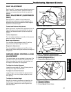
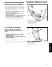
WARNING
Use two hands when adjusting the shock
springs. This will prevent the wrench from
slipping while pressure is being applied.
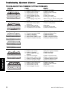
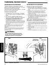
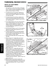
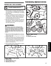
SUSPENSION ADJUSTMENT
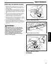
To adjust the upper mounting position:
1. Park machine on a flat, level surface. Disengage
the PTO, stop the engine and engage the parking
brake.
2. Raise the rear of the machine and secure with
jackstands. The jackstands must under the
bumper. Chock the front wheels to prevent the
machine from rolling.
3. Position the jack under the cross member that ties
the suspension arms together and slowly raise the
rear suspension to relieve the pressure on the
upper shock mounting bolts.
NOTE: This will require small adjustments to the
jack’s position. The shock should move freely on the
mounting bolt when the pressure is relieved.
4. Remove the upper shock mounting hardware and
pivot the shock to the position #2 (see Figure 35).
Adjust the jack to align the shock mounts to the
shocks.
5. Reinstall the upper shock mounting hardware and
tighten securely.
6. Remove the jack from under the suspension cross
member.
7. Remove the jackstands from under the machine.
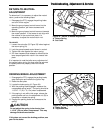
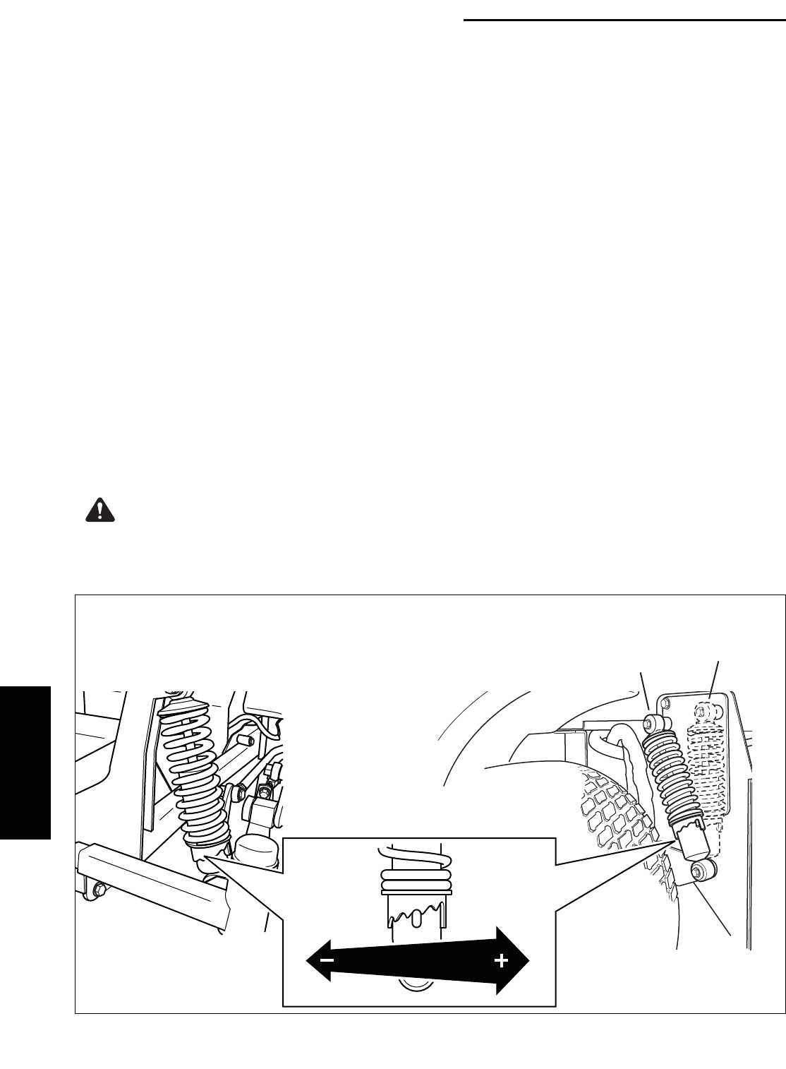
SUSPENSION ADJUSTMENT
The shock assembly can be adjusted to vary the
amount of pre-load applied to the springs. This allows
the operator to maintain the ride height.
Use less pre-load for light weight operators. Use more
pre-load for heavy weight operators.
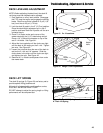
To adjust the spring pre-load:
1. Park machine on a flat, level surface. Disengage
the PTO, stop the engine and engage the parking
brake.
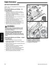
2. See Figure 35. Using the supplied spanner
wrench (p/n 5022853), insert the tip of the wrench
into the notch in the pre-load adjuster. While
holding the wrench with both hands, turn
CLOCKWISE to decrease the pre-load, turn
COUNTER-CLOCKWISE to increase the pre-load.
Make sure that for each pair of shocks that the left-
hand and right-hand are set to the same amount
of pre-load.
NOTE: Spanner wrench is located under the seat.
Rear tires must be removed to adjust the rear
suspension.
NOTE: It is recommended that the rear suspension
be adjusted stiffer due to the added weight of the
collection system.
FRONT REAR
Figure 35. Suspension Adjustment
POSITION #2
POSITION #1
(FACTORY SET)