


38
www.ferrisindustries.com
Troubleshooting
Troubleshooting, Adjustment & Service
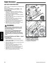
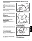
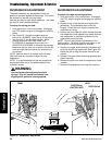
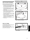
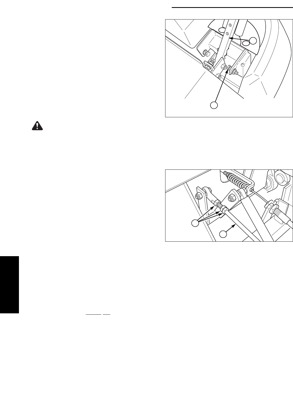
Figure 32. Neutral Adjustment
(RH side shown)
A. Adjustment Linkage Rod
B. Nuts
A
B
NEUTRAL ADJUSTMENT
If the tractor “creeps” while the ground speed control
levers are locked in NEUTRAL, then it may be
necessary to adjust the linkage rod.
NOTE: Perform this adjustment on a hard, level
surface such as a concrete floor.
1. Disengage the PTO, engage the parking brake
and turn off the engine.
2. There are three nuts (B, Figure 32) on the linkage
rod. The first two are to be used together to turn
the rod and the third (towards the front of the
machine) is used to lock the rod in place. Loosen
the jam nut that locks against the ball joint (B,
Figure 32) and turn the linkage rod (A) to adjust.
If the machine creeps forward, turn the rod
CLOCKWISE (while standing at the rear of the
machine, facing forward), if the machine creeps
backward, turn the rod COUNTER-CLOCKWISE.
3. Lock the jam nut (B) against the ball joint when
neutral is achieved.
NOTE: This adjustment should not be performed
while the machine is running. It may take several
attempts to achieved neutral, depending upon how
much the machine creeps.
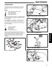
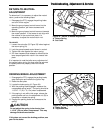
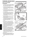
Figure 31. Top Speed Adjustment
A. Top Speed Adjustment Bolt
B. Control Lever Base
B
A
SPEED BALANCING ADJUSTMENT
If the rider veers to the right or left when the ground
speed control levers are in the maximum forward
position, the top speed of each of these levers can be
balanced by turning the adjustment bolt(s) (A, Figure
31). Only adjust the speed of the wheel that is
traveling faster.
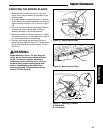
To Reduce the Speed of the Faster Wheel
1. Loosen the securing nut.
2. Turn the top speed adjustment bolt COUNTER-
CLOCKWISE to reduce the speed.
3. Retighten the securing nut when adjustment is
complete.
WARNING
DO NOT adjust the tractor for a faster overall
speed forward or reverse than it was designed
for.