www.extron.com
© 2008 Extron Electronics. All rights reserved.
Pricing and specifications may change without notice.
USA West
+1.714.491.1500 / +800.633.9876
+1.714.491.1517 FAX
USA East
+1.919.863.1794 / +800.633.9876
+1.919.863.1797 FAX
China
+86.21.3760.1568 / +400.883.1568
+86.21.3760.1566 FAX
Japan
+81.3.3511.7655
+81.3.3511.7656 FAX
Europe
+31.33.453.4040 / +800.3987.6673
+31.33.453.4050 FAX
Dubai
+971.4.2991800
+971.4.2991880 FAX
Asia
+65.6383.4400 / +800.7339.8766
+65.6383.4664 FAX
Continued
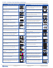
VTG 400d TesT PaTTerns
Circles
—
Using the circles as a guide, this pattern is used to evaluate
and adjust the geometry of the display device. The center crosshatch aids
in proper centering.
Safe Area (5%/10%)
—
This pattern is used to indicate the safe area of
display and inner safe area for titling within NTSC and PAL applications.
For graphics displays, this pattern serves as a guide for symmetrical
alignment of borders and text.
Focus Pattern
—
This pattern can be used to check display focus
and resolution.
16:9 Crop
—
When the border of this pattern is properly aligned at the
edges of a 4:3 screen, the two horizontal lines define proper centering
and shape of a superimposed 16:9 image.
4:3 Crop
—
When the border of this pattern is properly aligned at the
edges of a 16:9 screen, the two vertical lines define proper centering
and shape of a superimposed 4:3 image.
Rectangle/Square Crosshairs
—
This pattern can be used to
properly center the image and set geometry. For CRT-based
projectors, this pattern is used to check and adjust gross linearity
and static convergence.
4x4 Crosshatch
—
This pattern can be used to set up a scaler or video
processor for 2x or 4x zoom, or 1/4 or 1/16 downsizing. An application
of this crosshatch is setting up videowall displays.
Coarse Crosshatch
—
This crosshatch pattern can be used to set
projector focus and geometry. For CRT projectors, this crosshatch pattern
is for examining and adjusting both static and dynamic convergence.
Fine Crosshatch
—
This pattern has twice the number of horizontal
and vertical lines as the Coarse Crosshatch. It is useful for critical
convergence adjustments with CRT projectors and evaluating optical
qualities of projector lenses, such as chromatic aberration.
PLUGE
—
The vertical bars are used to set the black level (brightness),
while the horizontal bars aid in setting the contrast level for the display.
32-level Split Grayscale
—
With two opposing rows of 32 stepped bars
of gray between the lowest and highest levels, this pattern is used for
setting and assessing grayscale tracking, and evaluating contrast linearity
on display.
Extreme Grayscale
—
This pattern features shallow grayscale ramps
that allow for evaluation of display performance with subtle (very small)
grayscale level gradations.
Ramp
—
This pattern is used to evaluate the performance of a display or
video processor on the basis of its pixel bit depth capability. The pattern
should appear to be smooth, with no contouring or stepping.
Color Bars (8-color split)
—
This pattern is used for testing all of
the video color channels and setting video drive levels. It is also used
to check low frequency crosstalk between the red, green, and blue
color channels.
SMPTE Color Bars (with PLUGE pattern)
—
For NTSC video equipment,
the SMPTE color bars are used to set up tint and color, while the PLUGE
video pattern is for adjusting brightness and contrast.
EBU Color Bars (8-color full bars)
—
The EBU color bars are primarily
used to set up color for PAL video equipment.
80% Window
—
A window at 80% (80 IRE) video level, surrounded by
black, is used in fine tuning the color balance (or grayscale) of a display
with the aid of a color analyzer. The gain (or drive) setting is fine tuned
for each of the RGB color adjustments.
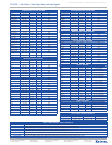
VTG 400d TesT PaTTerns
20% Window
—
A window at 20% (20 IRE) video level, surrounded by
black, is used in fine tuning the color balance (or grayscale) of a display
with the aid of a color analyzer. The bias (or offset) setting is fine tuned
for each of the RGB color adjustments.
Window (variable level)
—
The video level of the window can be adjusted
between 0% (0 IRE) and 100% (100 IRE) in 1% (1 IRE) steps. This pattern
is useful in fine tuning and evaluating grayscale performance of a display.
Flat Field (variable level)
—
This pattern is used to evaluate white
field uniformity. For RGB signals, each color channel can be selectively
enabled to assess color uniformity. The video level is variable between
100% (100 IRE) and 0% (0 IRE) in 1% (1 IRE) steps.
Flat Field with Targets (variable level)
—
This pattern is similar to Flat
Field, with targets added to support the ANSI measurement method for
determining display brightness.
Checkerboard (variable level)
—
This is the ANSI contrast ratio test
pattern, for measuring contrast ratio as well as adjusting and assessing
CRT display performance. This reversible pattern is variable in level
between 100% (100 IRE) and 0% (0 IRE) in 1% (1 IRE) steps.
Bounce (automatic)
—
The center window alternates between 90% and
10% average picture level at 0.5 second intervals. This pattern is used
for checking high voltage regulation on CRT displays, as well as black
level stability.
Bounce (manual)
—
This is similar to the automatic Bounce pattern,
but allows the user to manually toggle between 90% and 10% average
picture level.
Alternating Pixels
—
This one pixel “on,” one pixel “off” pattern is used
for assessing the performance of high resolution monitors and projectors,
EMI testing for worst case radiation, and pixel clocking and pixel phasing
adjustments on a digital display.
Frequency Sweep
—
These alternating “on” and “off” vertical bars
are used to evaluate the frequency response of an NTSC or PAL
video system.
Graphics Multiburst
—
This pattern of grouped alternating bars at
the highest “on” and lowest “off” video levels is used to test display
resolution capability for computer-video and HDTV.
Multiburst
—
This pattern of grouped alternating bars at the highest “on”
and lowest “off” video levels with increasing frequency is used to test
bandwidth performance for NTSC and PAL video.
Alternating Pixels (2-dimensional)
—
This offset, one pixel “on”, one
pixel “off” pattern is used for fine-tuning pixel clocking and pixel phasing
adjustments for high resolution digital displays.
Multipulse
—
This pattern is used to measure the frequency response
and group delay of the NTSC/PAL transmission channel.
Transient Response
—
The high and low levels bars against the
gray background are used for evaluation of transient response of the
video signal.
Contrast Transfer Function (CTF)
—
This pattern is for evaluation of
total video system response. The VTG 400 LCD display provides an
indication of contrast transfer percentage when the user has matched
the brightness of the horizontal lines to that of the vertical lines.
H Pattern
—
This pattern is used to check or evaluate video clamping
stability, focus for projectors, and video pulse response, as well as
to simulate text. The user can toggle between white-on-black and
black-on-white.
Hum Bar Test (variable level)
—
This pattern is used to reveal the
presence of any hum bars which indicate interference attributable to the
video signal or the equipment. The test pattern level is adjustable from
1% to 100%.
VTG 400D
—
Test Patterns, Video Output Rates, and Audio Signals
teSt GeneratorS & MeaSureMent productS
682


