


- 37 -
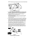
NOTE: The nuts to the rear of the unit on each rod have left-hand threads.
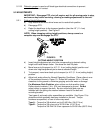
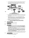
FIGURE 14
RH MOTION CONTROL ADJUSTMENT
f) Start engine. Brake must be engaged and motion control levers out to
start engine. Operator does not have to be in the seat because of the
jumper wire being used. Run engine at full throttle and release brake.
g) The reverse indicator spring must be correct before the following
adjustments can be made. See Section 5.2.10.
NOTE: The motion control lever needs to be in neutral while making
any necessary adjustments.
The left rod assembly controls the left wheel and the right rod assembly
controls the right wheel.
h) Bring the RH motion control lever into the neutral position. Adjust RH pump
control rod length by rotating the double nuts on the rod in the appropriate
direction until the wheels slightly creep in reverse. (See Figure 14). Move
the motion control lever to the reverse position and while applying slight
pressure to the lever, allow the reverse indicator spring to bring the levers
back to neutral. The wheel must stop turning or slightly creep in reverse.
When adjustment is complete, tighten lock nuts onto ball joints.
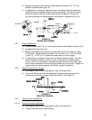
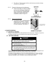
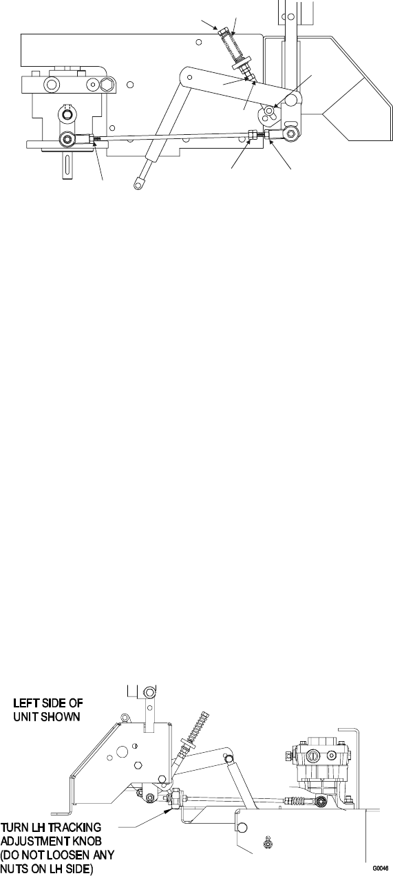
i) Bring the LH motion control lever into the neutral position. Adjust the LH
pump control rod length by rotating the tracking adjustment knob in the
appropriate direction until the wheels slightly creep in reverse. Move the
motion control lever to the reverse position and while applying slight
pressure to the lever allow the reverse indicator spring to bring the levers
back to neutral. The wheel must stop turning or slightly creep in reverse.
See Figure 15.
FIGURE 15
LH MOTION CONTROL ADJUSTMENT
TURN BOLT
HERE
LOOSEN HERE
(LEFTHAND THREAD)
END OF
SLOT
REVERSE
INDICATOR
TURN HERE
TO ADJUST
LOOSEN
HERE
LOOSEN HERE
(RIGHTHAND THREAD)
YOKE