


- 34 -
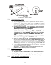
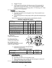
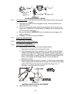
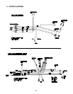
FIGURE 12
BLADE ENGAGEMENT LINKAGE
5.2.3 PTO Safety Switch: Mounted to a tab on the inside lefthand side of the fuel tank
support.
a) Stop engine and wait for all moving parts to stop. Remove ignition key or
spark plug wire(s).
b) With PTO disengaged and the bellcrank touching the rear of the slot in the
engine deck, adjust the PTO safety switch (if needed) until the bellcrank arm
is 5/16” from the switch body.
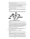
c) Be sure the bellcrank DOES NOT touch the switch body or damage to the
switch could occur.
d) Retighten PTO switch mounting hardware.
5.2.4 Engine to Cutter Deck Belt:
No adjustment necessary.
5.2.5 Pump Drive Belt Tension Adjustment:
No adjustment necessary.
5.2.6 Hydro Drive Linkage Adjustment:
a) Adjust Speed Control Linkage and Neutral Safety Switch
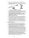
1. Stop engine and wait for all moving parts to stop.
2. Move the speed control lever (located on the console) to the full forward
position and check the orientation of the tabs on the ends of the speed
control crank (Figure 14). These tabs should be pointing straight down at
the 6 o’clock position or slightly forward. Adjust the threaded yoke at the
bottom of the speed control linkage (Figure 14) until the tabs are
positioned correctly.
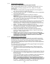
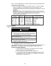
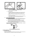
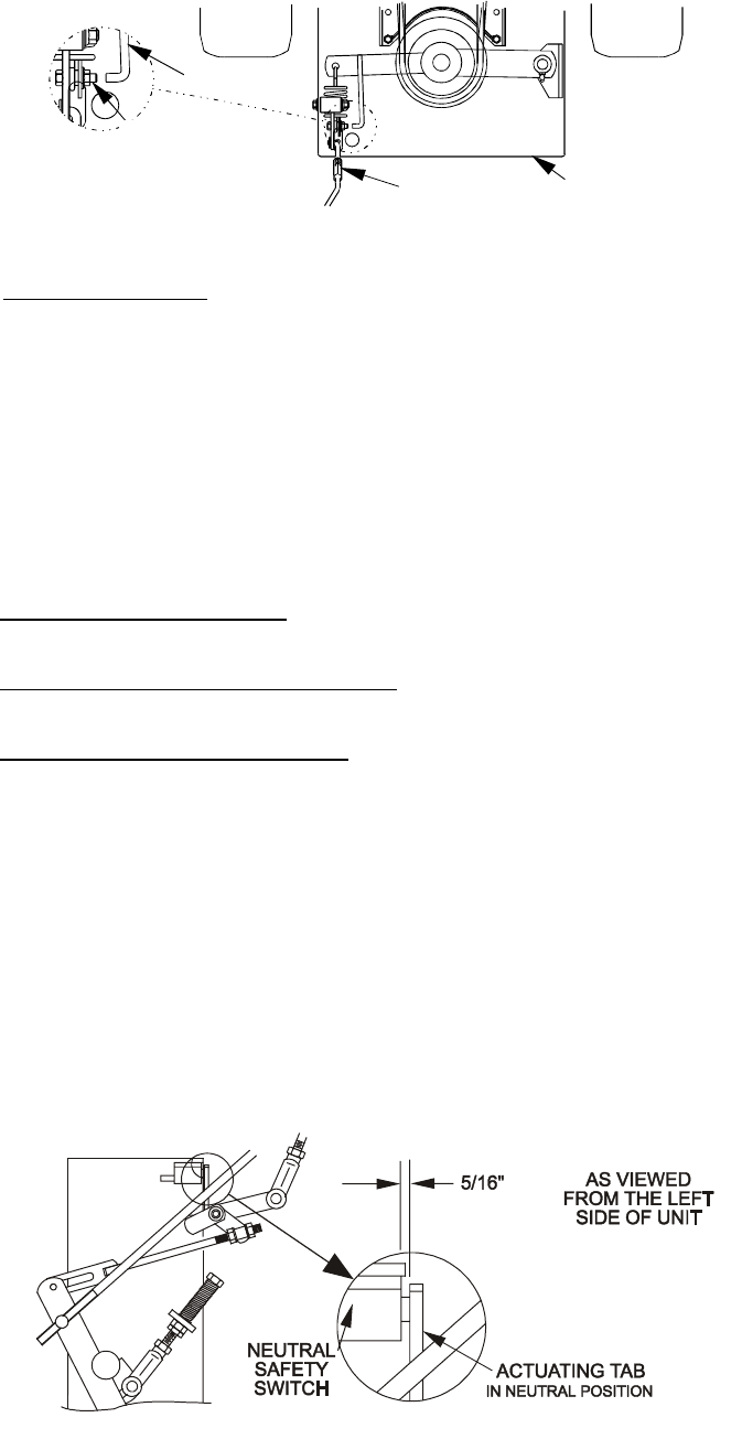
3. Pull the speed control lever back to neutral. Check that the neutral safety
switch actuating tab has depressed the plunger of the switch so that there
is about 5/16” between the tab and the switch (See Figure 13). If
necessary, move the switch fore and aft.
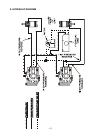
FIGURE 13
NEUTRAL SAFETY SWITCH ADJUSTMENT
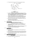
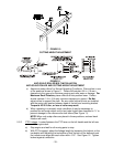
b) Adjust Neutral Control Linkages
Align Bolt to
Indicator
within 1/16”
Indicator
Turnbuckle
Engine Deck