


- 14 -
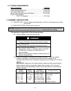
CAUTION
POTENTIAL HAZARD
♦ If the ignition is in the “ON” position there is potential
for sparks and engagement of components.
WHAT CAN HAPPEN
♦ Sparks could cause an explosion or moving parts
could accidentally engage causing personal injury.
HOW TO AVOID THE HAZARD
♦ Be sure ignition switch is in the “OFF” position before
charging the battery.
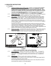
3.2.3 Connect the negative battery cables.
NOTE: If the positive cable is also disconnected, connect the positive (red)
cable to the positive terminal on the battery first, then connect the negative
(black) cable to the negative terminal on the battery. Reinstall battery cover.
NOTE: If time does not permit charging the battery, or if charging equipment is
not available, connect the negative battery cables and run the vehicle
continuously for 20 to 30 minutes to sufficiently charge the battery.
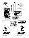
3.3 Remove and open the bolt bag.
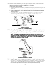
3.4 Loosen the 5/16" hardware at the two (2) discharge chute hinge points so that the
deflector is snug, but can be moved up and down freely.
3.5 Refer to Parts Manual to help you identify and locate parts and their proper position.
3.6 Apply retaining adhesive “Fel-Pro ProLock Retaining I or Retaining II” or “Loctite RC
609 or 680” on the two threaded studs from the bolt bag and install into the two left
holes underneath fuel tank. Install the fuel tank on top of the fuel tank support with the
studs going through the slots in the support. Install two 5/16 x 3/4 screws with a 5/16
SAE flat washer and 5/16 lock washer into the threaded holes in the right side of the
fuel tank. Do not over tighten. Place a 5/16 SAE flat washer, then a spring, over
each of the studs and fasten with a 5/16 nyloc nut. Tighten 5/16 nyloc nut fully then
back off a 1/2 turn. This is to allow for normal fuel tank expansion and contraction with
changes in temperature and fuel levels. Do not over tighten.
3.7 Attach the fuel tank hose to the tank fitting and secure with the clamp provided.
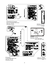
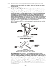
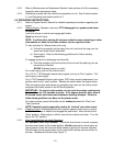
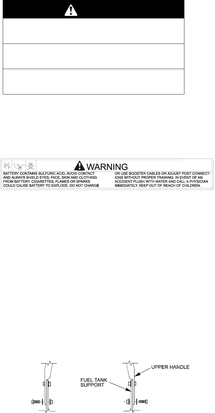
3.8 Position the lower end of the handle assembly on the outside of the upper rear section
of the fuel tank & handle support. Install four 3/8-16 x 1" bolts (with four spring disk
washers against the head of each bolt) from the outside in. Secure using four 3/8"
whizlock nuts on the inside of each handle support and tighten until the spring disk
washers are flat (See Figure 1).
FIGURE 1
UPPER HANDLE MOUNTING