


- 35 -
1. Raise the rear of the machine up onto jack stands high enough to raise
the drive wheels off of the ground.
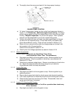
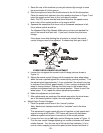
2. Start the engine and move the throttle ahead to the full throttle position.
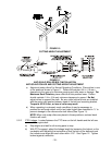
Place the neutral lock latches in the drive position as shown in Figure 7 and
move the speed control lever to the “mid-speed” position.
Note: The OPC levers must be held down whenever the speed control
lever is out of the neutral position or the engine will kill.
3. Squeeze the respective drive lever until an increased resistance is felt,
this is where neutral should be.
For Standard Pistol Grip Models: Make sure you have not reached the
end of the neutral lock latch slot. If you have, shorten the drive lever
linkage.
If the wheel turns while holding the drive lever in neutral, the neutral
control linkages need to be adjusted. If wheels stop then go to step 7.
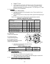
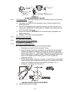
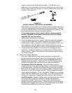
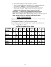
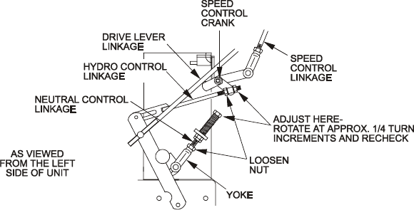
FIGURE 14
HYDRO DRIVE LINKAGE ADJUSTMENT
4. Loosen the nut against the neutral control linkage yoke as shown in
Figure 14.
5. Adjust the neutral control linkage until the respective drive wheel stops
when the lever is pulled against the neutral spring (neutral position). Turn
the adjusting bolt approximately 1/4 turn clockwise if the wheel is turning
in reverse or turn the bolt approximately 1/4 turn counter-clockwise if the
wheel is turning forward. Release the drive lever to the forward drive
position and squeeze back into the neutral position. Check to see if the
wheel stops. If not, repeat the above adjustment procedure.
6. Make this adjustment on both sides.
7. After adjustments are made and the wheels stop when the drive levers
are in the neutral position, tighten the nuts against the yokes.
c) Adjust Hydro Control Linkages:
1. Place the speed control lever in the “neutral” position.
Note: Neutral lock latches should still be “unlocked” and in the drive
position.
This adjustment is again made with rear of machine on jack stands and
engine running at full throttle. OPC levers will have to be held down
whenever speed control lever is moved out of the neutral position.
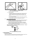
2. Loosen the front nut on left hydro control linkage as shown in Figure 14.
Turn the rear control linkage adjusting nut counter-clockwise until wheel
rotates forward. Turn the rear nut of left control link clockwise 1/4 of a
turn at a time, stopping to move the speed control forward and back to