


- 17 -
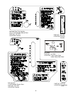
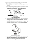
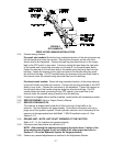
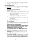
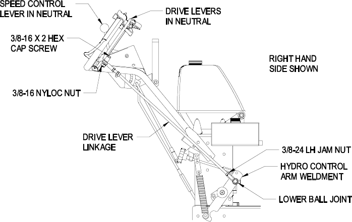
FIGURE 6
ECS HANDLES
DRIVE LEVER LINKAGE INSTALLATION
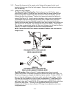
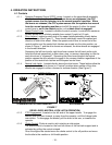
3.14 Connect wiring harness.
For recoil start models: Route the long unattached portion of the wiring harness up
the left handle and under the console. Connect the connector on the end of the
shorter lead to the keyswitch. Connect the two flag terminals that are in the longer
lead to the OPC switch in any order. Continue routing this lead down the right side
of the handle and connect the connector on the end of it to the park brake switch.
Fasten the harness to the left hand side of the handle using two large ties from the
bolt bag. Fasten the harness to the right hand side of the handle using two small
ties from the bolt bag. On ECS models fasten the harness to the two small holes in
the channel under the console using two small ties from the bolt bag.
For electric start models: Route the long unattached portion of the wiring harness
up the left handle and under the console. Connect the two flag terminals to the OPC
switch in any order. Connect the connector to the keyswitch. Fasten the harness to
the left hand side of the handle using two large ties from the bolt bag. On ECS
models fasten the leads connecting to the OPC switch to the small hole in the
channel under the console using a small tie from the bolt bag.
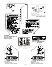
3.15 If machine is shipped without muffler installed, install muffler with hardware provided.
3.16 SERVICE ENGINE: Refer to Engine Owner’s Manual.
3.17 SERVICE HYDRAULIC OIL
The machine is shipped with hydraulic oil filled to the top of the baffle in the
reservoir. Run the machine for approximately 15 minutes to allow any extra air to
purge out of the hydraulic system. Check hydraulic reservoir and if necessary fill the
reservoir to the appropriate level with Mobil 1 15W-50 synthetic motor oil. See
Section 5.1.8
3.18 GREASE UNIT: NOTE: UNIT IS NOT GREASED AT THE FACTORY.
Refer to 5.1.14, for locations and grease amounts.
3.19 Follow pre-start instructions as outlined in 4.2.
NOTE: After starting the engine and engaging the hydro drive, if either of the
drive wheels acts sluggish or will not rotate at all, stop engine and refer to
Section 5.1.10 on the Hydraulic System Air Purge procedure.
3.20 Perform any needed adjustments as outlined in the Adjustment Section.