


Maintenance
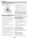
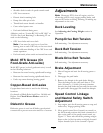
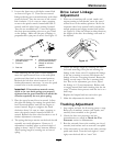
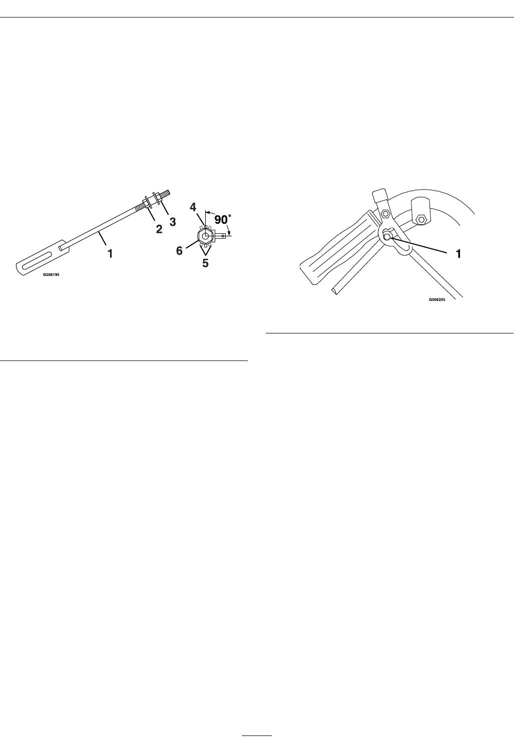
2. Loosen the front nut on left hydro control link
as shown in Figure 15. Turn the rear control
linkage adjusting nut counterclockwise until wheel
rotates forward. Turn the rear nut of left control
link clockwise 1/4 of a turn at a time, stopping
to move the speed control forward and back to
neutral, until left wheel stops rotating forward.
Turn the nut an additional 1/2 turn and tighten
the front jam nut making sure not to put a bind
on the linkage. Make sure at part of linkage is
perpendicular to pin part of swivel. See Figure 15.
Figure 15
1. Left Hydro Control Link
(left side shown)
4. Linkage is perpendicular
to pin (correct position)
2. Front nut 5. Linkage in incorrect
position
3. Rear nut
6. End view of swivel
After adjusting the left hydro control linkage,
move the speed control lever to the mid-speed
position and then back to the neutral position.
Recheck the left drive wheel rotation to see if
further adjustment is necessary - be sure the speed
control lever is in the neutral position.
Important: If inconsistent neutral occurs,
check to be sure both springs are properly
tightened on the speed control lever under the
console–especially the rear pivot spring.
3. Place the speed control lever in neutral. Adjust
the right side linkage by turning the quick track
knob counterclockwise until the tire begins to
rotate forward. Begin to retighten the knob
clockwise about 1/4 turn at a time, stopping to
move the speed control forward and back to
neutral. Recheck the drive wheel rotation to see if
further adjustment is necessary.
4. The spring that keeps tension on the knob should
normally not need adjustment. However, if
adjustment is needed, adjust to where length of
spring is about 1 inch (2.5 cm) between washers.
Adjust spring length by turning nut at front of
spring.
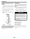
Drive Lever Linkage
Adjustment
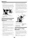
1. With rear of machine still on jack stands and
engine running at full throttle, move the speed
control lever to the midway position. Move the
respective drive lever upward until it reaches the
neutral position and engage neutral lock latches
see Figure 16. If the tire rotates in either direction,
the length of the drive lever linkage will need to
be adjusted.
Figure 16
2. Adjust the linkage length by releasing the drive
lever and removing clevis pin and rotating the
linkage in the lower swivel. Lengthen the linkage
if the tire is turning in reverse and shorten the
linkage if the tire is creeping forward. Rotate the
linkage several turns if the tire is rotating fairly
fast. But as the adjustment gets closer, adjust
the linkage in 1/2 turn increments. Release and
re-engage neutral lock latch checking that the tire
stops. Continue these process until the tire is at a
dead stop.
Replace the hairpin back into each clevis pin.
3. Make this adjustment for both sides.
Tracking Adjustment
1. Stop engine and wait for all moving parts to stop.
Raise rear of machine, remove jack stands, and
carefully lower machine to the ground.
2. Check the drive tire pressures and tire
circumferences as stated in Check the Tire
Pressures section in Maintenance.
3. Run the unit and observe the tracking on a level,
smooth, hard surface such as concrete or asphalt.
4. If the unit tracks to one side or the other, turn the
quick track knob. Turn the knob right to “steer”
right, turn the knob left to “steer” left.
31